

1 Executive Summary
Sweco has been instructed by SSE to carry out an assessment of delivery routes for abnormal transformer loads for three substation locations and HGV access to two trenched section access points.
The aim of the assessment is to identify any potential obstructions and areas of over‑run and over-hang for the safe delivery of abnormal indivisible loads along the existing roads and provide proposals for the permanent access roads to the given locations. For the purpose of this report the routes have been termed as below:
- Substation Location 3
- Substation Location 8 and 9
- HGV - Cable Road Crossing 1
- HGV - Cable Road Crossing 2
A swept path analysis using Auto Track has been undertaken for each delivery route. A walkover survey has been undertaken to identify additional obstructions and record any measurements where applicable. Results from the swept path analysis and walkover survey have been recorded on drawings and summarised within this report. In addition, the walkover survey was recorded using dashcam equipment and issued to SSE separately.
No topographical data was available during the assessment. This should be obtained and used to ensure there is no risk of grounding for the preferred delivery route. Note, the walkover survey did not highlight any obvious locations where grounding would be a concern.
It is recommended the following structural assessments are undertaken to fully evaluate each route.
Substation Location 3
Structural assessment of road bridge crossing railway before proposed permanent access road. Railway bridge west parapet also to be dismantled. Initial approvals from Network Rail and Transport Scotland will be required.
Substation Location 8 and 9
Structural assessment of culvert crossing below road approaching substation location. Note that no information was determined on the details of the culvert due to overgrown bushes and limited access.
HGV - Cable Road Crossing 1
Structural assessment of road bridge crossing railway before trenched cable road crossing location.
HGV - Cable Road Crossing 2
Structural assessment of road bridge crossing watercourse before trenched cable road crossing location. Note that limited details and dimensions of the bridge were obtained due to restricted access.
The capacity of manholes along each route should be confirmed. Additionally, any bridge or culvert crossing along the A1 should also be confirmed (out with the boundary limits of this report). Note Sweco have been advised not to consult with local roads authority, network rail etc. at this stage.
For undersized or unclassified manhole covers, a temporary steel plate rated to D400 loading in accordance with BS EN 124 should be designed as a minimum during the temporary work stage.
A cost estimate (+25%/-15%) for the new access road construction and improvements to current infrastructure has been assessed using values calculated from Spon’s Civil Engineering and Highways Work Price Book, the Estimator’s Pocket Book and information provided to Sweco by contractors.
A summary of the cost estimate for each substation route is presented below.
Substation Access Road Construction Cost Estimate
Substation | Estimated Construction Cost Range | |
Substation Location 3 | £506,243 | £862,806 |
Substation Location 8 | £187,111 | £278,978 |
Substation Location 9 | £225,646 | £348,842 |
It is advised to obtain a more detailed cost estimate from several contractors once topographical data and ground investigation information are made available. Note prices will vary between contractors and are subject to market conditions.
2 Introduction
2 Introduction
Seagreen Charlie Wind Energy Limited and Seagreen Delta Wind Energy Limited are developing the Seagreen 2 and Seagreen 3 Offshore Windfarms respectively, in the Firth of Forth.
It has been identified the export cable from Seagreen 2 will make landfall south of Dunbar and connect to the grid at Branxton.
A previous study into the preferred location for the substation was undertaken which identified sites primarily on the basis of topography to minimise ground works requirements.
Since the initial study, the footprint of the substation has increased and locations 8 & 9 are currently the preferred options when utilising Landfall 3 considering topography, access, impact on local residents and other constrains such as historic monuments.
When considering the cable route from Landfall 5, the preferred substation is at Location 3. Given the restrictions with topography at location 3, the required construction lay-down area will need to be situated approximately 500m away, a new access road would be required.
The three proposed substation locations and abnormal delivery routes are shown in Figure 2‑1. The proposed delivery route for substation 8 and 9 is similar. As such it be considered as one within the context of this report.
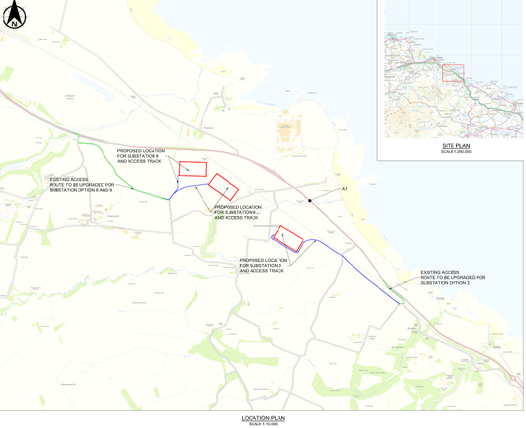
Figure 2‑1 Substation Location and Access Routes
2.1 Scope of Document
2.1 Scope of Document
Sweco has been instructed to carry out an assessment of the delivery route for the three proposed substation locations and two trenched section access points on behalf of SSE. The purpose of this report is to evaluate substation delivery routes for abnormal and HGV access from the A1.
The routes consider the existing roads and include proposals for the permanent access roads to the substation location for delivery of the transformer.
In addition, access to trenched sections of the cable route from Substation 8 and 9 via HGV (44 tonnes) is included. The locations of the trenched cable crossings are presented in Figure 2‑2.
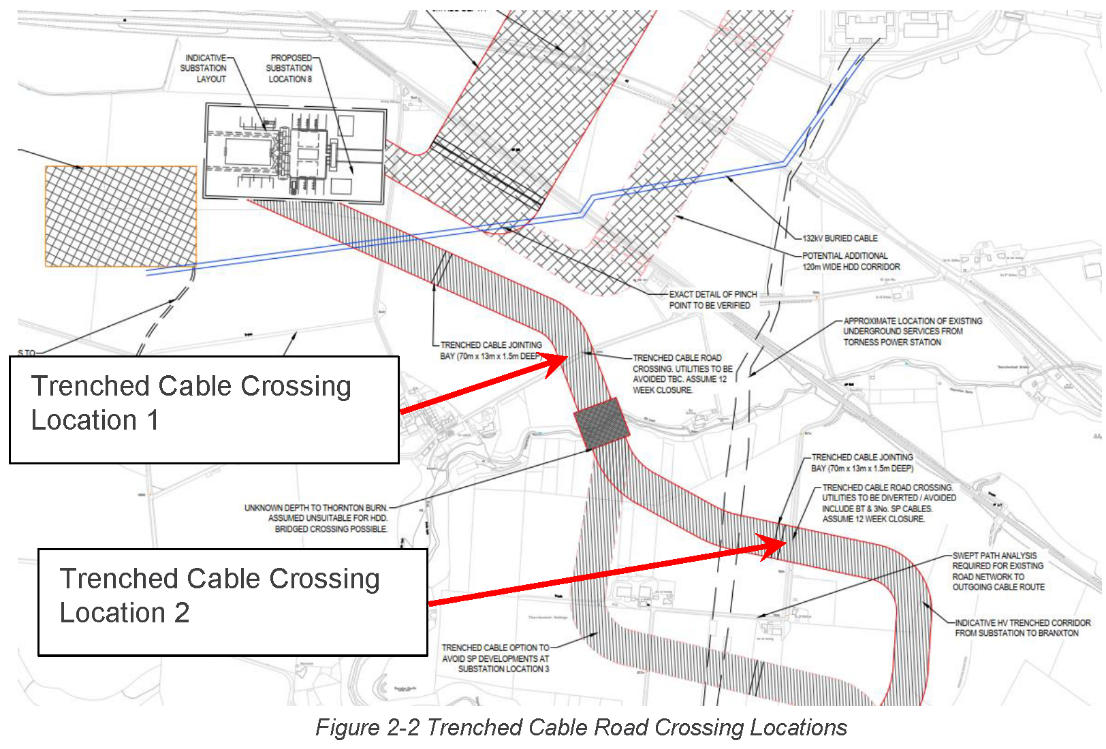
Figure 2‑2 Trenched Cable Road Crossing Locations
2.2 Methodology
2.2 Methodology
The study used Auto Track to provide a swept path analysis of all potential access routes along existing and proposed roads. Identified areas of concern were then investigated by two Sweco engineers during a route walkover survey to obtain further information and measurements where required.
The swept path analysis identifies the road edges and areas of over-run and over‑hang for the given vehicle dimensions outlined in Section 2.4.
The walkover survey identified additional obstacles including locations of overhead lines, trees, bridge parapets, manholes, potholes and steep embankment batter. Vehicle clearance checks were also performed on structures such as bridges.
Photographs taken during the walk over survey are presented in Appendix C. Where appropriate clearances have been recorded and highlighted on the swept path analysis drawings. Locations where alterations are required have also been identified. A tabulated summary of each route and the required improvements is presented in Section 3.
At the time of the swept path analysis, topographical data was not provided, and therefore a vertical clearance check has not been carried out. However, the walkover survey did not indicate any obvious locations where grounding would be a concern. It is still advised that a check is performed to ensure there is no risk of grounding for the preferred delivery route at a later stage.
A video survey of each proposed route was recorded during the walkover survey and has been issued to SSE separately.
2.3 Delivery Routes and boundary limits
2.3 Delivery Routes and boundary limits
The boundary limits of this report are described in Table 1 and illustrated in Figure 2‑3 to Figure 2‑5.
It has been assumed that all sections of the A1 are suitable for abnormal loads including transformer components. However, it should be confirmed that any bridge or culvert crossing is suitable for the given delivery loads.
Table 1 – Delivery Route Boundary Limits
Route | Start | Finish |
Substation Location 3 | Bildean Junction A1 southbound | Substation 3 site entrance |
Substation Location 8 & 9 | Innerwick Junction A1 southbound | Substation 8 & 9 site entrance |
HGV - Cable Road Crossing 1 | Thorntonloch Junction A1 southbound | Trenched cable road crossing 1 |
HGV - Cable Road Crossing 2 | Thorntonloch Junction A1 southbound | Trenched cable road crossing 2 |
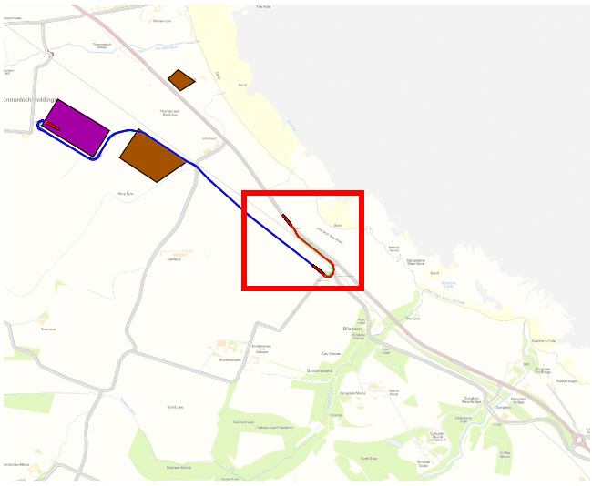
Figure 2‑3 Substation 3 Delivery Route

Figure 2‑4 Substation 8 & 9 Delivery Route
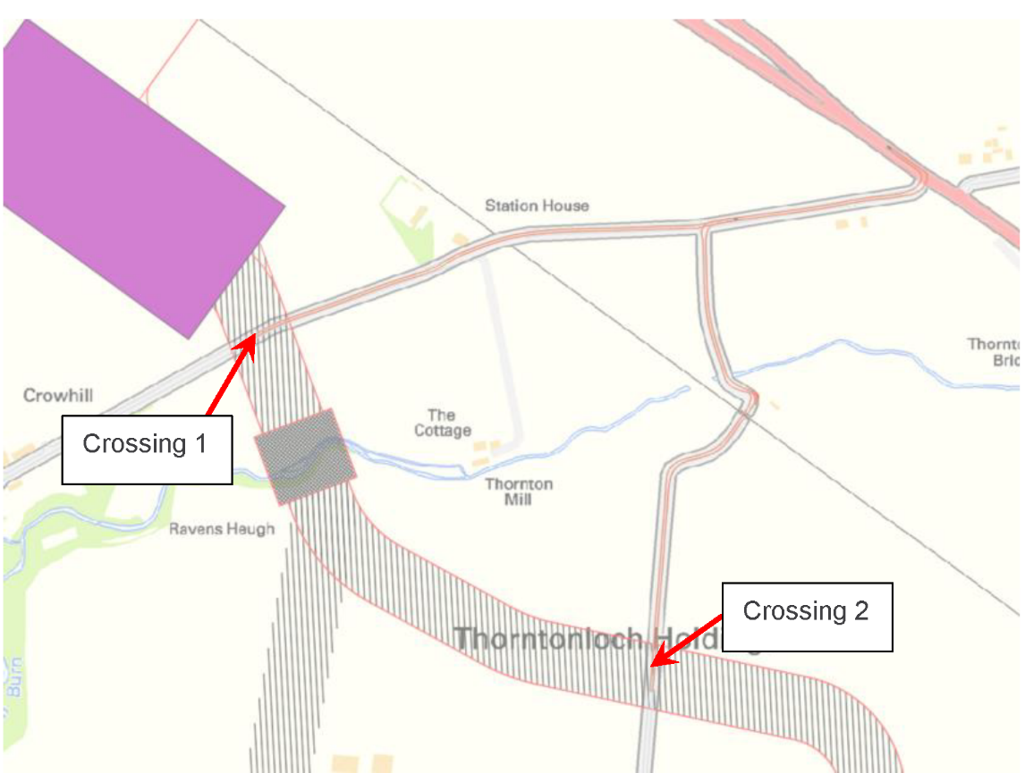
Figure 2‑5 HGV - Cable Road Crossing 1 and 2 Delivery Route
2.4 Delivery Vehicles
2.4 Delivery Vehicles
2.4.1 Transformer Delivery Vehicle
Specific details for the transformer delivery vehicle have been provided by SSE. This includes vehicle dimensions and axel loadings. The specific details have been used as input to the swept path analysis in Auto Track. Details of the vehicle provided by SSE are presented in Appendix A.
2.4.2 HGV (44 tonnes)
Details for a 44 tonnes HGV have been extracted from the Auto Track library. This has been used as input to the swept path analysis along the HGV delivery routes. Details of the proposed HGV are presented in Figure 2‑6.
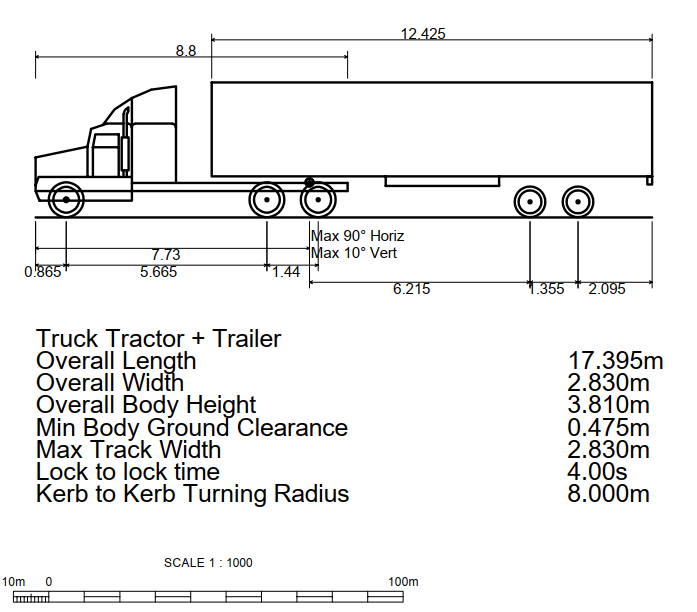
Figure 2‑6 HGV (44 Tonnes) Details
3 Swept Path Analysis Results
3 Swept Path Analysis Results
The swept path analysis highlighted physical obstructions and areas of over-run and over‑hang for each delivery route. These areas have been dimensioned on drawings in Appendix B.
A summary of drawing included in Appendix B are listed in Table 2.
Table 2 - Drawing List
Drawing Title | Drawing Number |
Location Plan | 65201721-DRG-101 |
Substation 8 & 9 Existing Road Improvement Plan Sheet 1 | 65201721-DRG-102 |
Substation 8 & 9 Existing Road Improvement Plan Sheet 2 | 65201721-DRG-103 |
Substation 8 & 9 Existing Road Improvement Plan Sheet 3 | 65201721-DRG-104 |
Substation 8 Proposed Road Improvement Plan | 65201721-DRG-105 |
Substation 9 Proposed Road Improvement Plan | 65201721-DRG-106 |
Substation 3 Existing Road Improvement Plan Sheet 1 | 65201721-DRG-107 |
Substation 3 Proposed Road Improvement Plan Sheet 2 | 65201721-DRG-108 |
Substation 3 Proposed Road Improvement Plan Sheet 3 | 65201721-DRG-109 |
Substation 3 Proposed Road Improvement Plan Sheet 4 | 65201721-DRG-110 |
44 Tonne HGV Existing Road Improvement Plan Sheet 1 | 65201721-DRG-112 |
44 Tonne HGV Existing Road Improvement Plan Sheet 2 | 65201721-DRG-113 |
44 Tonne HGV Existing Road Improvement Plan Sheet 3 | 65201721-DRG-114 |
The physical obstructions and constraints along each route including indicative details of measures required to mitigate against each are presented in Table 3 to Table 6.
For clarity, photographs taken during the walkover survey of each obstruction or constraint are referenced and included in Appendix C.
3.1 Substation Location 3
3.1 Substation Location 3
Table 3 - Substation Location 3 Delivery Route Summary
Ref | Drawing | Chainage | Description | Photo |
3.1.1 | 62501721-DRG-107 | 60 | Manhole load capacity to be confirmed. | 1 |
3.1.2 | 62501721-DRG-107 | 80 | Signposts/bollard need to be removed and reinstated post delivery | 2 |
3.1.3 | 62501721-DRG-107 | 370 | Stone wall to be removed prior to delivery | 3 |
3.1.4 | 62501721-DRG-107 | 400 | Railway bridge to be structurally assessed | 4 |
3.1.5 | 62501721-DRG-107 | 400 | Railway bridge west parapet to be | 5 |
3.1.6 | 62501721-DRG-107 | 420 | Armco barrier to be removed prior to delivery | 6 |
3.1.7 | 62501721-DRG-107 | 440 | Route enters private property. Road make up to be determined based on geotechnical survey of land. Existing fenceline at entrance/exit to be removed. |
|
3.1.8 | 62501721-DRG-107 | 440 | Old Signpost to be removed. May be of local | 7 |
3.1.9 | 62501721-DRG-107 | Circa 450 | Bustop/Sign/wall to be dismantled prior | 8 |
3.1.10 | 62501721-DRG-108 | 960 | Proposed X-road with existing road would involve substantial earthworks in comparison to alternative routes. Recommend redirecting route to have this junction south of mature trees due to steep embankment at proposed crossover. | 9/10 |
3.2 Substation Location 8 & 9
3.2 Substation Location 8 & 9
Table 4 - Substation Location 8 & 9 Delivery Route Summary
Ref | Drawing | Chainage | Description | Photo (Appendix 3) |
3.2.1 | 62501721-DRG-102 | 100 | Right Turn of A1. Fenceline to be removed. | 1 |
3.2.2 | 62501721-DRG-102 | 100 | Right turn off A1, temporary overrun area | 2 |
3.2.3 | 62501721-DRG-102 | 100 | Right Turn off A1, Road sign/Island to be removed | 3 |
3.2.4 | 62501721-DRG-102 | 200 | Left Turn to main access route, large overrun area to be built up. | 4/5 |
3.2.5 | 62501721-DRG-102 | 200 | Left turn to main access route, Manhole load capacity to be check | 6 |
3.2.6 | 62501721-DRG-102 | 450 | Existing fenceline to be removed | 9 |
3.2.7 | 62501721-DRG-102 | 450 | Overrun area to be granular surfaced | / |
3.2.8 | 62501721-DRG-102 | 700 | Overhead lines ok | 10 |
3.2.9 | 62501721-DRG-103 | 760 | Manhole load capacity to be checked | / |
3.2.11 | 62501721-DRG-103 | 770 | Fenceline to be removed to accommodate | 11 |
3.2.12 | 62501721-DRG-103 | 880 | Overrun area to be granular surfaced | 12 |
3.2.13 | 62501721-DRG-103 | 1040 | Culvert to be structurally assessed. No information was determined on the details of the culvert due to limited access. | 13 |
3.2.14 | 62501721-DRG-103 | 1070 | Overrun area to be granular surfaced | / |
3.2.15 | 62501721-DRG-103 | 1180 | Overrun area to be granular surfaced | / |
3.2.16 | 62501721-DRG-103 | 1200 | Manhole load capacity to be checked | 14 |
3.2.17 | 62501721-DRG-103 | 1230 | Fenceline to be removed to accommodate | 15 |
3.2.18 | 62501721-DRG-104 | 1650 | overhead lines avoided | 16 |
3.3 HGV – Cable Road Crossing 1
3.3 HGV – Cable Road Crossing 1
Table 5 - HGV - Cable Road Crossing 1
Ref | Drawing | Chainage | Description | Photo (Appendix 3) |
3.3.1 | 62501721-DRG-112 | 490 | Road over railway bridge to be structurally assessed for HGV | 1/2 |
3.4 HGV – Cable Road Crossing 2
3.4 HGV – Cable Road Crossing 2
Table 6 - HGV - Cable Road Crossing 2
Ref | Drawing | Chainage | Description | Photo (Appendix 3) |
3.4.1 | 62501721-DRG-112 | 175 | Road over water crossing to be structurally assessed for HGV. Limited details and dimensions of the bridge due to restricted access. | 1 |
3.4.2 | 62501721-DRG-112 | 200 | Stone wall to be removed and earthworks required for vehicle over run | 2 |
3.4.3 | 62501721-DRG-112 | 225 | Road below railway bridge suitable for HGV | 3/4 |
4 Structural Constraints
4 Structural Constraints
For each proposed delivery route, a structural assessment is required to ascertain the suitability of the structures along the route prior to delivery. The structures include bridges, culverts and watercourse crossings. Capacity of manholes highlighted in Section 3 along each route should also be confirmed. Note Sweco have been advised not to consult with local roads authority, network rail etc. at this stage.
The following sections highlight each structure that requires an assessment for the given route.
4.1 Substation Location 3
4.1 Substation Location 3
The delivery route to the proposed substation location 3 will require the delivery vehicle to traverse a stone railway bridge. The location of the railway bridge is shown in Figure 4‑1.
Railway bridge west parapet to be dismantled prior to delivery in addition to assessment of the bridge for the abnormal loads. Initial approvals from Network Rail and Transport Scotland will be required.
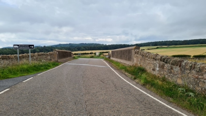
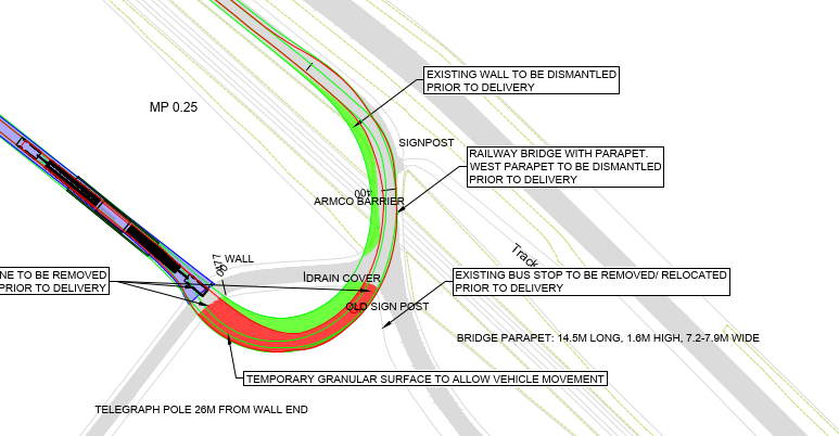
Figure 4‑1 Railway bridge Crossing for Delivery to Substation Location 3
4.2 Substation Location 8 & 9
4.2 Substation Location 8 & 9
The delivery route to the proposed substation location 8 and 9 will require the delivery vehicle to traverse a culvert. The location of the culvert is shown in Figure 4‑2. The make-up of the culvert could not be confirmed due to dense and overgrown vegetation.
An assessment of the culvert for the abnormal load is required. Note that no information was determined on the details of the culvert due to overgrown bushes and limited access.
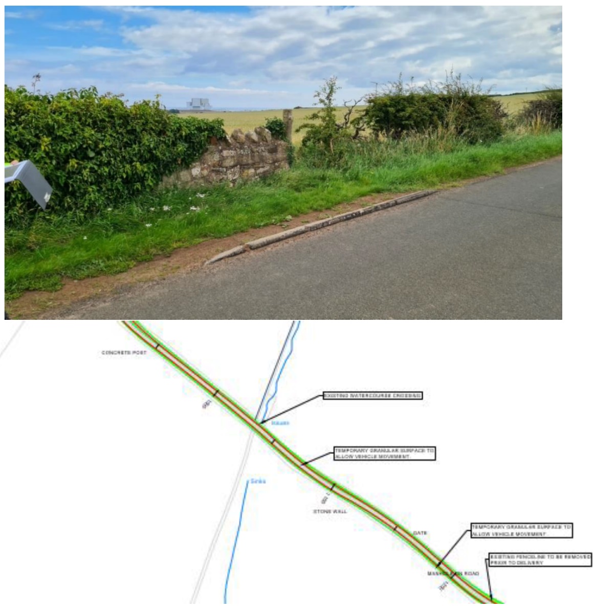
Figure 4‑2 Culvert Road Crossing for Deliver to Substation 8 & 9
4.3 HGV - Cable Road Crossing 1
4.3 HGV - Cable Road Crossing 1
The delivery route to the trenched cable road crossing 1 will required the HGV to cross a railway bridge. The location of the bridge is shown in Figure 4‑3.
An assessment of the railway bridge crossing for the HGV is required.
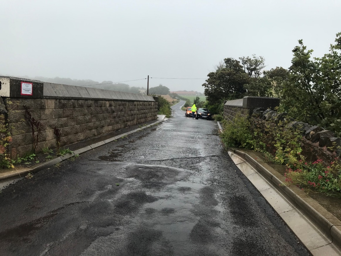
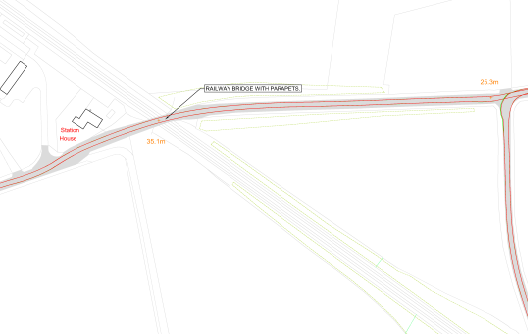
Figure 4‑3 Railway Bridge Crossing for Cable Road Crossing 1
4.4 HGV - Cable Road Crossing 2
4.4 HGV - Cable Road Crossing 2
The delivery route to the trenched cable road crossing 2 will require the HGV to cross a watercourse crossing. The location of the crossing is shown in Figure 4‑4.
An assessment of the watercourse crossing for the HGV is required. Note that limited details and dimensions of the bridge were obtained due to restricted access.
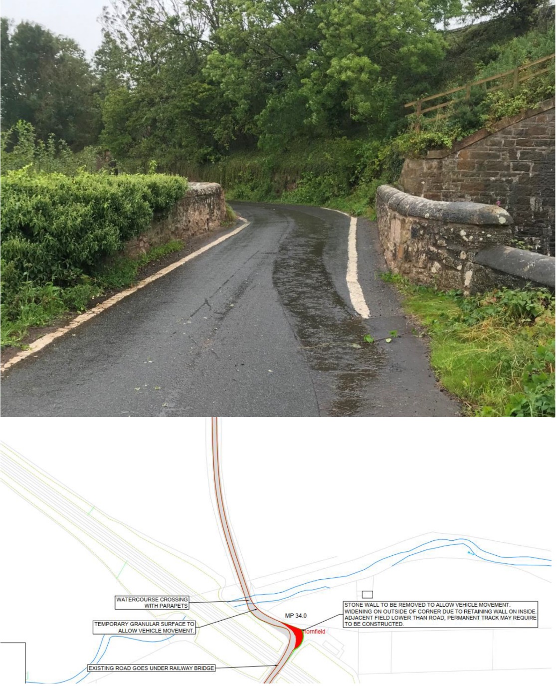
Figure 4‑4 Watercourse Crossing for Cable Road Crossing 2
5 Permanent Access Road Proposal
5 Permanent Access Road Proposal
No ground investigation reports have been provided at this stage with respect to design of the permanent access roads. Therefore, proposals for the following road make-up have been provided in appendix D:
- Floating access track (level or gently sloping topography);
- Founded access track (level or gently sloping topography);
- Founded access track – Track Construction Benched (on sloping topography).
6 Construction Cost Estimate
6 Construction Cost Estimate
A cost estimate (+25%/-15%) for the new access road construction and improvements to current infrastructure has been assessed using values calculated from Spon’s Civil Engineering and Highways Work Price Book, the Estimator’s Pocket Book and information provided by contractors.
A preliminary assessment of the permanent access road was undertaken in lieu of ground investigation information. This assessment considered data from British Geological Survey maps. Given the road construction cost is sensitive to change and accounts for most of the overall cost, a lower and upper bound cost was used in the estimations.
Areas of temporary granular fill are based on vehicle overrun only. Earthwork requirements are subject to more detailed review as part of route temporary works design.
An estimate of the costs for each substation route is presented in Table 7 with the detailed estimate presented in Appendix E.
Table 7 - Substation Access Road Construction Cost Estimate
Substation | Estimated Construction Cost Range | |
Substation Location 3 | £506,243 | £862,806 |
Substation Location 8 | £187,111 | £278,978 |
Substation Location 9 | £225,646 | £348,842 |
It is advised to obtain a more detailed cost estimate from several contractors once topographical data and ground investigation information are made available. Note prices will vary between contractors and are subject to market conditions.
7 Conclusion and Recommendations
7 Conclusion and Recommendations
7.1 Conclusions
7.1 Conclusions
It can be concluded from the swept path analysis that all substation / crossing locations are suitable, given the capacity of the railway bridges, culverts and watercourse crossings are assessed and the capacity is confirmed for the given loads. All proposed routes require widening for areas of over-run and improvements to remove obstacles for over-hang.
Substation location 3 may be less favourable given the extensive works required for access. This includes:
- 2145m of permanent access road which accounts for the majority of construction costs
- assessment of bridge deck and initial approvals from Network Rail and Transport Scotland required
- removal of the westerly parapet on the road bridge over the railway
- removal of street furniture including bus stop and signposts
- additional land purchase to accommodate wide swing required by access vehicle as identified in the swept path analysis
The proposed access route to Substation 3, running parallel to the railway track, would require significant amounts of cut material for the intersection to join the existing road at an appropriate level. This material then needs to be transported offsite. An alternative route has been indicated on the drawings which avoids the large cut volume. However, this alternative route may require additional land.
Substation location 8 and 9 are the preferred options given the lower cost of road improvements and permanent access road. Costs for substation location 8 and 9 are lower than Substation location 3 as the new access roads are shorter. Excluding the new access road, the largest anticipated cost for location 8 & 9 would be the widening at approximately chainage 200, where fill material is required to accommodate over-run.
Substation location 8 is less expensive than location 9 as the permanent access road is shorter at 384m compared to 597m.
An estimate of the costs for each substation delivery route is presented in Table 8.
Table 8 - Substation Access Road Construction Cost Estimate
Substation | Estimated Construction Cost Range | |
Substation Location 3 | £506,243 | £862,806 |
Substation Location 8 | £187,111 | £278,978 |
Substation Location 9 | £225,646 | £348,842 |
HGV delivery to cable road crossing 1 and 2 both require a structural assessment of the road bridge crossing over the railway and the watercourse crossing respectively. If satisfactory, both routes will be suitable for HGV delivery to the cable road crossings.
7.2 Recommendations
7.2 Recommendations
From the swept path analysis and walkover survey the following recommendations have been made to ensure safe delivery along each route:
- Topographical data and ground investigation information is required to refine the cost estimate for the proposed permanent access roads for each substation location.
- Ensure there is no risk of grounding for the preferred delivery route using topographical data.
- Confirm that any bridge or culvert crossing along the A1 (out with the boundary limits of this report) is suitable for the given delivery loads.
- An abnormal load assessment of the road bridge crossing the railway for substation location 3 is required.
- An abnormal load assessment of the culvert for substation location 8 and 9 is required.
- As part of the temporary works design, a steel plate rated to D400 loading in accordance with BS EN 124 should be designed for undersized or unclassified manhole covers as a minimum.
- A HGV load assessment of the road bridge crossing the railway for cable road crossing 1 is required.
- A HGV load assessment of the road bridge crossing the watercourse for cable road crossing 2 is required.
Appendix A – Vehicle Loads and Dimensions
Appendix A – Vehicle Loads and Dimensions
PDF document Open ▸
Appendix B – Swept Path Analysis Drawings
Appendix B – Swept Path Analysis Drawings
PDF document Open ▸
Appendix C – Route Walkover Photographs
Appendix C – Route Walkover Photographs
PDF document Open ▸
Appendix D – Permanent Road Access Proposal
Appendix D – Permanent Road Access Proposal
PDF document Open ▸
Appendix E – Permanent Access Road Cost Estimate
Appendix E – Permanent Access Road Cost Estimate
PDF document Open ▸