

5. Proposed Development Description
5.1. Introduction
- This chapter provides a description of the proposed Onshore Transmission Works (OnTW) (the Proposed Development) required to enable the grid connection for the Berwick Bank Wind Farm (the Project). This chapter also provides a description of the Planning Application Boundary and its geographical context (the ‘site’). This chapter includes details about the location, nature and extent of activities associated with the construction, operation and maintenance and decommissioning of the Proposed Development, all of which are located above (i.e., the landward side of) Mean Low Water Springs (MLWS).
- The Proposed Development comprises of onshore cables within a cable corridor from the landfall connecting to new onshore Electricity Transmission Buildings which would either be a high voltage alternating current (HVAC) substation or high voltage direct current (HVDC) converter station (referred to as ‘substation’ in this EIA Report) and the onward onshore cable corridor connecting to the SP Energy Networks (SPEN) Branxton Substation (Volume 2, Figure 5.1 Open ▸ ).
- A separate offshore EIA Report will describe offshore infrastructure including the Offshore Transmission Works (OfTW) of the Project and will be submitted to Marine Scotland – Licensing Operations Team (MS-LOT), accompanying the relevant consent and licence applications required for the marine environment. The offshore EIA Report provides details of the offshore infrastructure located below (i.e., the seaward side of) Mean High Water Springs (MHWS). The area between MHWS and MLWS (the intertidal area) is addressed where relevant, within both the onshore and offshore EIA Reports. Further details of the approach taken to the intertidal area is provided within Volume 1, Chapter 2, Section 2.4.10.
- The information provided within this chapter underpins the EIA and the associated planning application to East Lothian Council (ELC). This chapter presents the project maximum design scenario parameters (the project design envelope (PDE)) that have been considered in determining the potential likely significant effects of the Proposed Development.
- This chapter is supported by information contained within the following appendices:
- Volume 4, Appendix 5.1 Outline Construction Environmental Management Plan; and
- Volume 4, Appendix 5.2 Climate Assessment.
5.2. Site Description And Location
- The site is situated near Torness and the village of Innerwick, south-east of Dunbar located in East Lothian, Scotland (Volume 2, Figure 1.1). The centre of the site is OSGB36, British National Grid (BNG) 374080, 673982. The site is approximately 598 ha in size.
- The Proposed Development which has been evaluated in the EIA Report and presented in the planning application is shown on Volume 2, Figure 5.1 Open ▸ The proposed landfall is located north-west of Torness Power Station and Skateraw harbour. The onshore cable corridor is located between the landfall for approximately 1.5 km, connecting to the new onshore substation, located north-east of Innerwick. The onshore substation connects to the proposed SPEN Branxton substation to the south-east via a continuation of the onshore cable corridor for approximately 1.8 km.
- The extent of the site runs from the settlement of Branxton in the south, Bilsdean in the south-east, the coastline at Skateraw and Torness in the north, Oxwell Mains Cement Works and Quarry in the north-west and Fouracres in the west. The land on which the site is located is predominantly agricultural land with sparse settlements spread throughout, connected by small local roads and tracks. The A1 trunk road (A1(T)) and East Coast Main Line (ECML) railway cut through the site in a north-west to south-east direction running parallel to the coast. Torness Power Station (Nuclear) is located to the south-east of the proposed landfall at Skateraw.
- Ground levels within the site vary due to the sloping topography (west to east) and due to deeply incised glacial outwash valleys.
- The existing infrastructure within the site and adjacent area includes:
- Torness Power Station and associated infrastructure;
- Torness nuclear waste railway loading dock;
- The A1 (T);
- ECML railway;
- 400 kV overhead lines and underground cables at Branxton;
- Two existing cable sealing end compounds at Branxton;
- Innerwick electricity substation;
- Onshore electricity infrastructure, including Neart na Gaoithe (NnG) cable route and infrastructure;
- Local access roads; and
- Utilities, including drainage, water, gas, telecommunications and electricity services.
- Volume 1, Chapter 4 provides a summary of the site selection process and the environmental and engineering considerations which have been taken into account when defining the Proposed Development site.
5.3. Proposed Development
- Berwick Bank Wind Farm Limited (BBWFL) is a wholly owned subsidiary of SSE Renewables Limited and will hereafter be referred to as ‘the Applicant’. The Applicant proposes to submit a planning application under the Town and Country Planning (Scotland) Act 1997 (as amended) for the following OnTW:
- new onshore Electricity Transmission Buildings (HVAC substation or HVDC converter station);
- landfall works;
- onshore cables within a cable corridor between the landfall and the new onshore substation, and between the new onshore substation and the SPEN Branxton substation; and
- associated ancillary infrastructure.
- The locations, definitions and descriptions of the Proposed Development are provided in detail below and shown in Volume 2, Figure 5.1 Open ▸ A summary of the infrastructure needed for the Proposed Development, is provided in Table 5.1 Open ▸ below. The values shown represent the realistic worst-case values for the purposes of the EIA (“the maximum design scenario”). Whilst the design parameters are frozen, the detailed design within these parameters may be influenced by construction techniques. As noted in the sections above, the proposed Electricity Transmission Buildings would comprise of either a substation or converter station. The assessment covers the worst-case scenario and as such either a substation or converter station could be developed within the parameters of the EIA. The electricity transmission buildings are hereafter referred to as the “onshore substation” throughout the EIA Report.
- The locations of the Proposed Development and associated infrastructure would be subject to micrositing to take account of more detailed topographical and geotechnical surveys which would take place prior to construction commencing. Through this EIA and planning application the Applicant will seek agreement for micrositing as which allows for infrastructure to be moved by up to 50 m from that shown on the site layout. This would be with the approval of an Environmental Clerk of Works (ECoW), with input from site archaeologists, ecologists and any other relevant specialist supervising design and construction activities. Throughout the EIA assessment, the Applicant has accounted for micrositing.
- The Branxton substation is being developed by SPEN and is subject to a separate planning application. However, the potential cumulative impacts on relevant environmental receptors of the Proposed Development and the SPEN Branxton substation have been considered within the EIA.
Table 5.1 Proposed Development Infrastructure
5.3.1. Offshore Export Cables, Landfall And Transition Joint Bays
- At landfall, up to eight offshore export cables will come to shore and will be connected to the onshore cables via eight buried transition joint bays. The eight proposed transition joint bays will connect the offshore export cables and the onshore cables (Volume 2, Figure 5.5 Open ▸ ). Each transition joint bay will consist of an underground box-like structure that houses the cable joints. The box-like structures will be up to 13 m width by 3 m height, with all eight located within a single 25,610 m2 temporary trenchless technique e.g. Horizontal Directional Drilling (HDD), construction compound during landfall construction. (Volume 2, Figure 5.2 Open ▸ ).
- The proposed transition joint bays will be located approximately 130 m north-west of Skateraw harbour, on land used for agriculture. The coordinates for this landfall are BNG 373571, 675772 (Volume 2, Figure 5.2 Open ▸ ).
- The infrastructure which is associated with the transition joint bays and landfall will also include manhole covers, to cover the communications and link boxes, which may be fenced off for security. Other construction compounds measuring up to 8,220 m2 and a temporary material storage area of up to 3,615 m2 (Volume 2, Figure 5.2 Open ▸ ) are also proposed at landfall. Further details of temporary infrastructure proposed for the construction activities are provided in Section 5.4.
5.3.2. Onshore Cables
- This section details the onshore cable corridor of the Proposed Development.
From Landfall to Onshore Substation
- Following the connection of the offshore export cables to the onshore cables at the transition joint bays, the onshore cables will be installed underground through predominantly agricultural land, located between the coast at Skateraw and the ECML railway and A1 (T) (Volume 2, Figure 5.3 Open ▸ ). An increase in width from 18 m to 30 m of an existing culvert crossing of a tributary of the Dry Burn will be required to install and complete this section of the onshore cable installation (Volume 2, Figure 5.6 Open ▸ ). Following the Dry Burn, the onshore cables will be installed west of the residential properties at Skateraw, before crossing underneath the unclassified road (Volume 2, Figure 5.3 Open ▸ ). This section of cable corridor between the landfall, unclassified road and up to the ECML is proposed to be completed by an open trench technique.
- The proposed onshore cables will cross beneath the ECML railway and the A1 (T) and will require these two sections of work to be completed by a trenchless technique (e.g. HDD), with associated temporary trenchless technique compounds. There will be one trenchless technique compound located north of the ECML, two located in the agricultural land between the ECML and A1 (T), and one located south of the A1 (T) (Volume 2, Figure 5.3 Open ▸ ). The trenchless technique compounds will encompass a total area of up to 12,430 m2. The trenchless works under the ECML will have a depth up to 14 m and total length up to 170 m. The trenchless works under the A1 (T), which will also cross underneath the NnG cable corridor, will have a depth of up to 18 m and length of up to 170 m.
- Before connecting to the onshore substation, the proposed onshore cables will cross a minor burn which lies south of the A1 (T) and north of the onshore substation. It is proposed that the minor burn will be temporarily diverted which will allow for the open cut trenching technique and burying of this section of the cable to be undertaken.
- The onshore cables will then connect to the switchgear within the onshore substation via the northern edge of the onshore substation platform.
- For this section of the cable route a temporary construction compound is proposed between the ECML and A1 (T) which will be up to 3,300 m2.
- Several areas of proposed temporary material storage will be located along the cable corridor leading up to the onshore substation (Volume 2, Figure 5.3 Open ▸ ), requiring a total area of 16,955 m2 Further details of temporary infrastructure during construction, including access roads, are provided in Section 5.4.
Onshore Substation to SPEN Branxton Substation
- Following connection to the onshore substation, the onshore cables will exit the South of the substation by a trenchless technique (e.g. HDD), passing beneath an existing 132kV utility. The onshore cables will then be installed utilising an open trench technique in a southerly direction, through agricultural land southwest of Innerwick Castle and Thornton Glen. This section of cable route will cross two local roads before turning generally south-east and passing beneath Castledene Scheduled Monument (SM5849) utilising trenchless technique. The onshore cables then continue for a distance of approximately 330 m in open cut formation, before crossing Braidwood Burn via a cable bridge. From there, the cables will connect to the proposed SPEN Branxton substation, which is adjacent to the existing Innerwick sealing end compound (Volume 2, Figure 5.4 Open ▸ ).
- The onshore cables will require a trenchless technique (e.g. HDD) for installation at two locations between the onshore substation and the Branxton substation. The first, as mentioned above, is located where the onshore cable exits the onshore substation and is required to cross existing 132kV cables. There are existing overhead lines in the area. This trenchless technique will be to a depth of up to 10 m and length of up to 100 m (Volume 2, Figure 5.4 Open ▸ ). This will require two compounds of up to 9,950 m2 in total. The second trenchless crossing will pass beneath the Castledene Scheduled Monument (SM5849) and require two compounds of approximately 5,210 m2 in total. The trenchless technique (e.g. HDD) will have a depth up to 12 m and a total length of up to 190 m (Volume 2, Figure 5.4 Open ▸ ).
- An indicative diagram of the cable bridge crossing of the Braidwood Burn is shown in Volume 2, Figure 5.6 Open ▸ The cable bridge will be up to 40 m in length (headwall to headwall) and 10 m in width (span). It is anticipated that the final solution and detailed design of the Braidwood Burn crossing will be confirmed and agreed with ELC and Scottish Environment Protection Agency (SEPA) following ground investigations prior to construction. It is proposed that the final solution and detailed design for all water crossings will be addressed through an appropriately worded condition in order to ensure that the works comply with the Water Environment (Controlled Activities) (Scotland) Regulations 2011 (also known as the Controlled Activities Regulations (CAR)).
- The Braidwood Burn cable bridge crossing will be designed in accordance with SEPA guidance to allow for 1 in 200 year flow event and to allow for the safe passage of mammals and fish species. The cable bridge crossing will not be maintained for pedestrian or vehicle access and will be secured to prevent public access. Alternative means of crossing the Braidwood Burn such as trenchless technique (e.g. HDD) or overhead lines have been considered through the design process as detailed in Volume 1, Chapter 4. After consideration of these alternative means of crossing, a cable bridge is required in this location due to the constraints imposed to alternative methods by the steep topography, existing overhead lines, and cumulative restrictions of the proposed SPEN cable corridor to the west.
- Temporary construction compounds and material storage areas will be associated with the onshore cable corridor and cable bridge crossing (Volume 2, Figure 5.4 Open ▸ ). Further details of temporary infrastructure during construction, including access roads, are provided in Section 5.4.
5.3.3. Onshore Substation
- The onshore substation is defined as a permanent compound comprising elements of electrical infrastructure including buildings, which are required to facilitate connection to the national grid.
- The onshore substation is located at grid reference, BNG 373065, 674532, within an agricultural field, which is currently used for arable agriculture, on a northern facing slope approximately 700 m north-east of Innerwick settlement (Volume 2, Figure 5.7 Open ▸ and 5.8). The A1 (T) and the ECML railway are located 140 m and 210 m respectively to the north.
- The onshore substation will either be a high voltage alternating current (HVAC) substation comprising of internal and external HV equipment and Gas Insulated Switchgear; or a high voltage direct current (HVDC) converter station comprising of converter buildings, HV external equipment and Gas Insulated Switchgear. The onshore substation will comprise of electrical components for transforming the power supplied from the offshore wind farm (OWF) to the grid voltage and will be formed of a maximum of 18 buildings. The onshore substation will include operational buildings and facilities including car parking, security fencing and welfare facilities. The welfare facilities will be connected to a filtration system for foul drainage, which will be maintained by a licensed contractor and the contents disposed of at a licensed off-site location. Further details are provided in the Outline Site Waste Management Plan within the Outline Construction Environmental Management Plan (Volume 4, Appendix 5.1).
- The onshore substation footprint will be 97,500 m2 (maximum 390 m length by 250 m width) with internal buildings of a maximum height of 21 m. Associated lightning rods will be of an approximate tip height of 25 m. Further studies will be necessary to determine the final height of the rods, although it is likely to be less than 25 m. The finished platform level of the onshore substation will be 44.3 m above ordnance datum (AOD).
- Indicative layouts (HVAC and HVDC options) of the onshore substation are shown within Volume 2, Figure 5.9 This presents the anticipated layout for both an HVAC or HVDC substation. Details of the final design of all components of the substation are proposed to be agreed with ELC through discharge of planning conditions should planning permission be granted.
- A new permanent access road to the onshore substation will be required from a new junction onto the unclassified public road to the south-west of the onshore substation location (Volume 2, Figure 5.8 Open ▸ ). This new permanent access road will be a surfaced single carriageway road. It will be a private road and include appropriate drainage.
- Permanent and temporary drainage systems will be established around the onshore substation, including a permanent Sustainable Urban Drainage System (SuDS) pond to the east. Further details of the permanent drainage systems are provided within Volume 4, Appendix 11.2. A permanent access road to the SuDS Pond is proposed (Volume 2, Figure 5.10).
- There will be temporary construction compounds, material laydown areas and access routes associated with the onshore substation, as shown on Volume 2, Figure 5.7 Open ▸ Further details of all temporary infrastructure during construction are provided in Section 5.4.
5.4. Construction
- The construction stage of the Proposed Development is anticipated to take approximately 40 months with a proposed commencement date in 2024. Table 5.2 provides further details of the construction programme.
- The proposed construction methods for the Proposed Development are provided in sections 5.4.1 to 5.4.5.
5.4.1. Construction Access
- Temporary access routes will be constructed within the site along the length of the onshore cable corridor to provide access for construction vehicles to each specific section and to connect construction vehicles to the local public road network. Public road improvement works are required along the local road to the onshore substation. These will consist of the construction of passing places and road widening to accommodate the necessary construction and abnormal load traffic. Following construction, the areas will be reinstated to their original condition.
- Construction access points are provided at several locations along the onshore cable corridor (Volume 2, Figure 5.10 Open ▸ ). The temporary access roads will be formed of crushed stone / hard standing or tracked and will be maintained for the duration of the construction period as required Following construction, the temporary surface will be removed and the previous land use reinstated.
- The temporary access roads have been designed to minimise impacts on the local road network as far as possible. Traffic figures have been generated for the Proposed Development construction works (refer to Volume 1, Chapter 12 for further information). A Transport Assessment has been prepared in support of the application and provides greater detail on access routes to the site and potential impacts of construction and operation traffic (Volume 4, Appendix 12.1). The Applicant will ensure that all vehicles will be routed as agreed with ELC and Transport Scotland, to minimise disruption and disturbance to local residents. A provisional Outline Construction Traffic Management and Routeing Plan has been prepared and is provided as an appendix to the Transport Assessment (Volume 4, Appendix 12.1) which provides further details of proposed mitigation measures to be implemented during construction.
5.4.2. Offshore Export Cables, Landfall, And Transition Bays
- The offshore export cable will be brought to shore using trenchless technology (e.g. HDD). The offshore export cable will be pulled (e.g. via a winch from a platform at landfall or a drilling rig vehicle) from sea to land at the transition joint bays (Volume 2, Figure 5.2 Open ▸ ).
- The transition joint bays will be excavated by a mechanical excavator after which a concrete chamber will be constructed. A temporary structure will be placed on top of the excavated transition joint bays to allow a weatherproof working environment during cable jointing. A generator will be required to provide power supplies during jointing operations. Temporary security fencing and lighting will be constructed to enclose and secure the transition joint bays during construction. Following construction and installation, the transition joint bays will be backfilled with granular/reinstated excavated material, protective covers (where appropriate) and warning tapes, to avoid damage during any future excavations. Following completion of backfill, the native material (i.e., topsoil) will be replaced in line with an earthworks management plan that will be produced and agreed with ELC as detailed design information becomes available. Only minor structures will be visible above ground, such as manhole covers for the communications box and link boxes, low link pillar for earthing requirements and potential security fencing to enclose the communications and links boxes.
5.4.3. Onshore Cables
- Open cut trenching will be required for most onshore cable installations, with trenchless technology (e.g., HDD) required at the following locations:
- Landfall;
- To cross the ECML;
- To cross the A1 (T) and existing cable infrastructure (i.e. NnG onshore cable corridor);
- To cross the 132kV cables located to the South of the onshore substation; and
- To cross a Scheduled Monument.
- The extension or replacement of an existing culvert is required to enable the onshore cables to cross a tributary of the Dry Burn watercourse at landfall, and a cable bridge crossing is required to enable the onshore cables to cross the Braidwood Burn. The crossing of the minor watercourse directly north of the onshore substation will require temporary diversion or over pumping during construction.
Open Cut Trenching
- Open cut trenching will be used to install the onshore cables for the majority of the onshore cable corridor. Following trenching, the onshore cables will be laid in ducts and buried where possible to depths of up to 2.5 m. A typical cross section of open cut trenching is provided in Volume 2, Figure 5.11 Open ▸
- The onshore cables will be installed in discrete sections along the onshore cable corridor. Installation works at each section will consist of several activities including construction of associated temporary access roads, installation of pre-construction, temporary and post construction land drainage, excavation of the onshore cable trench, laying of ducts, onshore cable pulling and laying, onshore cable jointing, backfilling of materials and reinstatement to the previous land use where appropriate. The onshore cables will also go through testing and commissioning phases.
- Before installation works begin at each section, the topsoil across the construction area will be removed using mechanical excavators and stored along the cable corridor for later replacement when works are complete. If required, aggregate (on a geotextile where soft ground is encountered) may be laid over a section of the exposed subsoil for the temporary access road. Mechanical excavators will be used to dig the cable trench. Once complete each section of the onshore cables (stored on a drum) will be lifted from the delivery truck and placed into position at the end of the trench. The onshore cables will then be winched through the open trench, to a joint bay at the end of the section.
- Once the onshore cables are installed, the trench will be backfilled with stabilised backfill (i.e., cement bound sand) and granular/reinstated excavated material, protective covers (where appropriate) and warning tapes, to avoid damage during any future excavations. Following completion of trench backfill, native material (i.e., topsoil) will be replaced. Previously excavated material will be used to backfill the cable trench wherever possible to minimise the amount of material to be disposed of off-site. Any stockpiling of excavated material along the onshore cable corridor will be sited within the site.
- Following backfill of the onshore cable trench, the land will be reinstated to allow a return to its former use.
- Some sections of the onshore cable corridor may require trenching through public roads. Three public roads will be crossed via open cut trenching. This includes the public road north of the ECML, and two unclassified public roads south of the onshore substation (Volume 2, Figure 5.10 Open ▸ ). Access will be maintained through traffic management and temporary road diversions which will be agreed with ELC prior to construction commencing. Cables will need to be installed below existing utilities in the local roads which may involve temporary works and agreement with the relevant statutory utility providers.
- Open cut trenching may be used to enable the onshore cables to cross features such as fences, hedgerows and walls. Such features will be fully reinstated where possible once the installation works are complete (for example, fences and walls will be rebuilt and any gaps in the hedgerow will be replanted).
Trenchless Technology (e.g., HDD)
- Trenchless technology (e.g. HDD) is proposed to be used along sections of the cable route to go under sensitive features. One method of trenchless technology which has been investigated is HDD. HDD is a method of underground cable installation, the principle of which is to install a duct by drilling underground between two points. Electrical cables are installed within the duct and the installation is completed without the need to excavate an open trench between the two points.
- The trenchless technique compounds which are required for the Proposed Development will likely comprise of a construction area containing equipment including a drill rig, an electrical generator, a water tanker, and a mud recycling unit. Drilling mud, containing bentonite (a naturally occurring absorbent clay) and fresh water, will be used to aid the drilling process. Drilling mud will be recycled on site within a contained system throughout the drilling process to minimise fresh water usage. Upon completion of the installation process, surplus drilling mud will be reused on site.
- The drilling/installation process will comprise the following stages:
- A small diameter pilot hole will be drilled for the purpose of defining the path of the duct into which the cable is to be installed. Separate pilot holes will be drilled for each cable.
- A reamer will then be pulled back through the pilot hole enlarging the diameter of the hole as it progresses. This may have to be repeated a number of times, depending on the nature of the ground through which it passes, in order to enlarge the pilot hole diameter sufficiently to accommodate the duct.
- The ducts will then be attached to the reamer and pulled through the widened pilot hole. This operation may be done with the onshore cable inside the duct or alternatively after the duct is installed, the onshore cables may then be winched through the ducts.
- When cable pull-through is complete, the onshore cables will be secured in place.
- A typical cross section of HDD trenchless technique methodology is provided in Volume 2, Figure 5.12 Open ▸
Watercourse Crossings
- Watercourse crossings have been minimised as far as reasonably possible through the design process, however, they will be required at the locations outlined below along the onshore cable corridor (Volume 2, Figure 5.13 Open ▸ ).
- An upgrade to an existing culvert crossing of a tributary of the Dry Burn is required during landfall construction works. The existing culvert may be widened or replaced to form a suitable working corridor width. The culvert is anticipated to either be a circular concrete pipe culvert (as currently in-situ) or an arch culvert and will be designed in accordance with SEPA Good Practice Guidance (2010).
- A new cable bridge crossing will be constructed over the Braidwood Burn (Volume 2, Figure 5.6). It is anticipated that all materials for the construction of the Braidwood Burn crossing will be delivered and worked from the northern side of the watercourse. These works will comply with a Safe System of work in order to ensure the appropriate clearance envelope of the overhead lines is maintained.
- The minor watercourse directly north of the onshore substation will be crossed (using open trench techniques) with buried onshore cables and is anticipated to require temporary diversion or over pumping during construction. The watercourse will be restored following completion of construction works.
- Where necessary CAR licences for work affecting watercourses will be applied for post-consent, prior to construction commencing and once final design has been reached.
5.4.4. Onshore Substation
- The following subsections detail the works proposed for the construction of the onshore substation (Volume 2, Figure 5.7 Open ▸ ).
- Construction of the onshore substation will require the following:
- Construction of spread foundations to support small structures
- Construction of hardstanding areas i.e. pavements and car parking;
- Construction of foundations to support the high loads of the transformers, reactors and other HV electrical plant;
- Construction of a finished platform through completion of earthworks operations to provide a level substation footprint. The exact depth and volume of cut and fill soil which is associated with the flat platform will be determined following more detailed investigations. Depending on the topography this may require the construction of retaining structures;
- Installation of utilities and services;
- Construction of permanent drainage (SuDS pond);
- Construction of permanent access roads to the onshore substation and SuDS pond;
- Construction of substation infrastructure including switchgear buildings;
- Landscaping and restoration of land adjacent the substation
- Construction of surface water and foul water drainage provision; and
- Installation of fencing, site floodlights and security measures.
- Once the access road to the onshore substation is established, enabling works will be progressed, including; ground works, earthworks (substation and SuDs pond), establishing equipment foundations, compacting, surfacing and establishing drainage systems.
- A temporary construction compound will be required nearby during construction (Volume 2, Figure 5.7 Open ▸ ). Further details of the proposed temporary construction compound is provided in Section 5.4.5.
5.4.5. Temporary Construction Compounds, Material Storage And Lay Down Area
- To facilitate construction activity of the Proposed Development, a series of temporary construction compounds, material storage and lay down areas will be erected across the site as shown on Volume 2, Figure 5.1 Open ▸ , and maintained for the duration of the construction period. The total area required for the construction compounds is shown in Table 5.1.
- The temporary construction compounds will house temporary portable cabin structures to be used as the main site office and welfare facilities, including toilets, kitchens, and the provision of sealed waste storage and removal. Temporary construction compounds will also be used for the storage of infrastructure components, parking for vehicles, storage for tools and small parts, as well as oil and fuel storage. Temporary construction compounds will have security fencing erected for the duration of the construction programme (Table 5.2). Temporary lighting will also be required. Directional lighting will be used to minimize light spill beyond the compound.
- The surface of the construction compound will be crushed stone. As with the rest of the temporary works, topsoil will be relocated, stored and reinstated following the completion of works.
- The material storage and lay down areas will be established through stripping of the topsoil and subsoil material, depths of which will be governed by the design / required bearing capacities at these locations. Prior to construction an earthworks management plan will be produced and shared for agreement with ELC. This will detail how the soils will be stripped, segregated, stored, and reinstated following completion of the works.
5.4.6. Construction Traffic
- Access for construction of the Proposed Development (onshore substation, cable landfall and onshore cable route) will be via the A1 (T) and subsequently by the local road network. The anticipated routes are described as follows:
- Onshore Substation – construction traffic will depart the A1(T) at Innerwick junction and will continue towards the onshore substation site via the unclassified road to the north of Innerwick.
- Cable Landfall – construction vehicles will leave the A1(T) at access to Skateraw and will continue towards the cable landfall site via the unclassified road to Skateraw and subsequently via the existing access track beyond the entrance to Skateraw beach car park.
- Onshore Cable Route – There will be several anticipated site accesses associated with the onshore cable route construction, which are as follows:
– Cable (1 – 3) Sites – Construction vehicles will leave the A1 (T) at the A1 (T) / Skateraw priority junction and will continue towards the site accesses via the unclassified road to Skateraw.
– Cable (4) Site – Larger construction vehicles will leave the A1 (T) and access the site via a newly formed left-in access junction from the A1 (T). They will egress in the same manner, due to the height constraints imposed by the Network Rail underbridge, turning left only onto the A1 (T). Lighter vehicles will egress the same way they entered, via the road which crosses under the East Coast Main Line (access C3), and subsequently through Skateraw and the A1 (T) / Skateraw priority junction.;
– Cable (5) Sites – Construction vehicles will leave the A1 (T) at Innerwick junction and join the local road network. Approximately 70 m after the Innerwick junction, vehicles will turn left towards Crowhill / Oldhamstocks. Approximately 180 m along this road, vehicles will access the Cable (5) site via a newly upgraded access junction. Vehicles will access /egress the site at this location.
– Cable (6 – 8) Sites – Construction vehicles will leave the A1 (T) at Innerwick junction and join the local road network. Approximately 70 m after the Innerwick junction, vehicles will turn left towards Crowhill / Oldhamstocks and will continue along this road until they reach their respective accesses; and
– Cable (9) Site – Construction vehicles will leave the A1 (T) at Innerwick junction and join the local road network. Approximately 70 m after the Innerwick junction, vehicles will turn left towards Crowhill / Oldhamstocks and will continue along this road and across Thornton Bridge towards the site access. Should access for larger vehicles over the Thornton Bridge not be feasible, they are anticipated to access this area of the site via C8 and over the proposed cable bridge crossing.
- Public road improvements (PRI’s) will be necessary to enable access for abnormal indivisible load (AIL) vehicles. Namely, these consist of substation material/component deliveries (i.e., transformers) and cable drum deliveries. Full details of the required improvements can be found in Volume1, Chapter 12. These will be confirmed and agreed with ELC prior to commencement of construction.
- During construction, a general road wear and tear review would be undertaken with the road authorities, with interim reviews undertaken by the Principal Contractor. Any damage to road infrastructure caused directly by construction traffic would be made good, and street furniture that is removed on a temporary basis would be fully reinstated.
- There would be a regular road edge review and any debris and mud would be removed from the public carriageway to keep the road clean and safe during construction, until the construction junction and immediate access track works are complete.
- An Outline Construction Traffic Management Plan (CTMP) has been submitted with the EIA and is provided in Volume 4, Appendix 12.1. A detailed CTMP will be submitted to and agreed with ELC prior to commencement of development.
5.4.7. Working Hours
- Planning permission will be sought for 24-hour, 7 days per week construction working hours. The 24-hour construction period is anticipated to be only necessary for the trenchless technique (e.g. HDD) solutions. This is on the basis that the trenchless installations (drilling and ducting) need to be completed as a continuous activity from the entry point to the exit point. Predominantly, this is to maintain integrity of the borehole (i.e., reduce risk of collapse), but also to ensure the operations can be continuously monitored to ensure no settlement limits are exceeded as part of the planned methodology. Once the boreholes are drilled (and ducts installed) the ducts will maintain the borehole integrity. Dependant on the location of the trenchless crossing the cable installation may also need to be completed in a single operation, and back grouted to fully encapsulate the cables within the ducts.
- Consultation with Transport Scotland and Network Rail with regards to the crossings of the A1 (T) and ECML has identified a requirement for continuous 24-hour working at these locations to ensure that the monitoring regime(s) can be effectively implemented during the works to ensure safeguarding of these transport routes. 24-hour working is also required at landfall to ensure alignment with the offshore transmission works construction programme. The trenchless technology (e.g. HDD) crossings under the 132 kV cables and the Scheduled Monument at Castledene are anticipated to maintain standard working hours of 07:00 to 19:00 as far as reasonably practicable on the basis that these are much shorter and shallower trenchless technologies (e.g. HDDs). There would only be a requirement to extend outwith standard working hours if there are unforeseen circumstances which may prevent drilling operations from stopping. All other construction works would maintain 07:00 – 19:00 working hours. As such, any necessary night time working will be minimised as far as reasonably practicable.
- The noise produced by construction has been assessed within Volume 1, Chapter 9. This assessment shows that the works can be undertaken in compliance with the noise limits set by ELC.
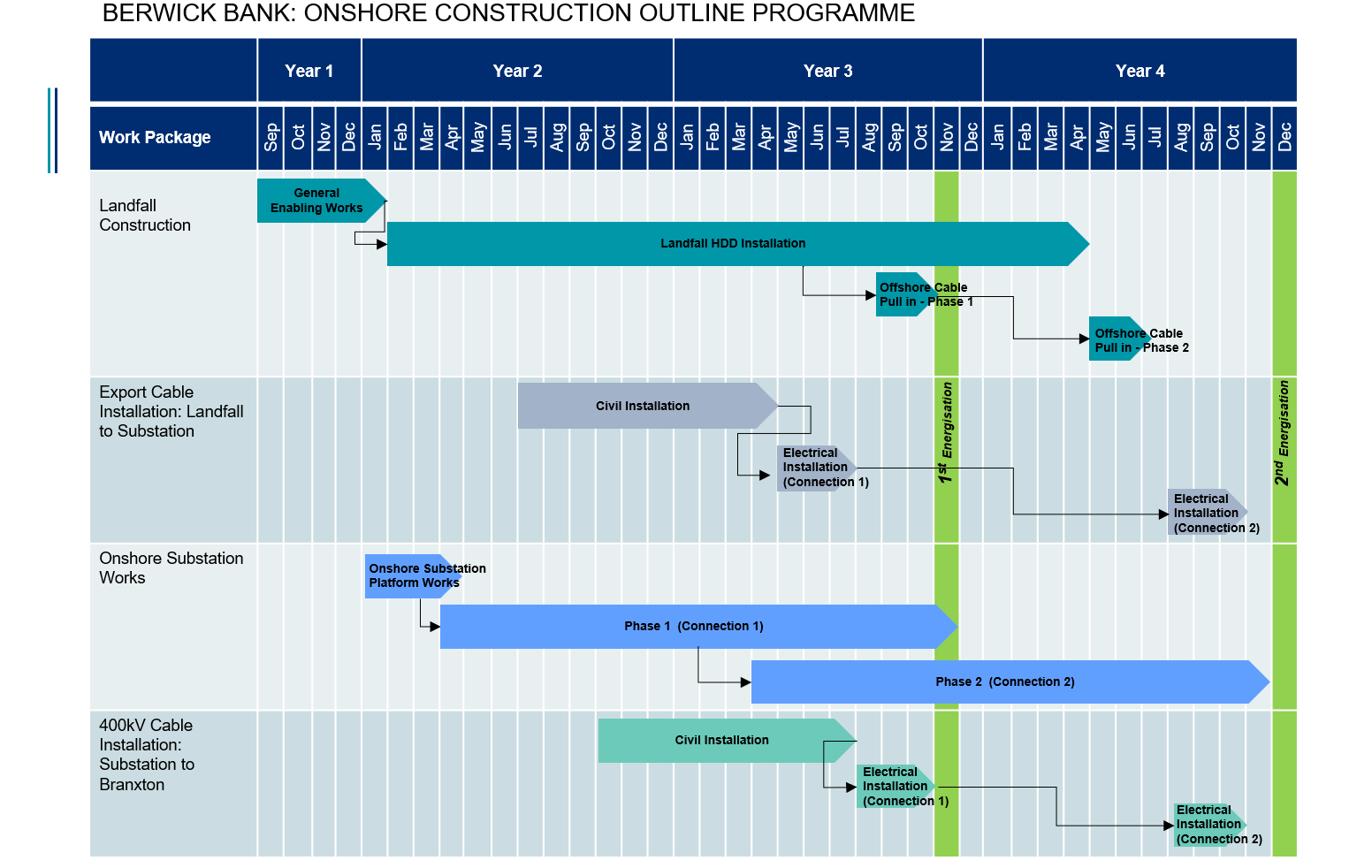
5.4.8. Construction Programme
- An outline of the programme for construction of the Proposed Development is provided in Table 5.2 below.
- The indicative commencement and completion dates, together with estimated durations of key construction activities, have been used to inform the assessment of construction impacts.
- The Proposed Development will be constructed over a period of 40 months, including general enabling works which are expected to be required up to six months ahead of the commencement of construction. Most activities will have a maximum total duration of 30 months or less. Although construction activities will typically occur sequentially there are expected to be periods where certain construction activities occur concurrently. In particular, it is expected that construction activities at the landfall (trenchless technology (e.g. HDD) installation) will occur at the same time as construction of the onshore substation. The onshore substation will also be constructed in two phases to align with the connection dates included in the grid connection agreements (2026 and 2027).
Table 5.2 Construction Outline Programme
5.4.9. Construction Environmental Management Plan
- The following sections set out proposed construction, waste and environmental management procedures to be adopted. Further details of mitigation and management measures during construction are provided within the topic specific chapters.
- An outline Construction Environmental Management Plan (CEMP) is provided in Volume 4, Appendix 5.1 The outline CEMP sets out the principles and framework that will be applied during construction. A detailed CEMP will subsequently be submitted to ELC for approval prior to construction commencing.
- The detailed CEMP shall describe how the Applicant will ensure suitable management of, but not limited to, the following environmental issues during construction of the Proposed Development:
- Noise and vibration;
- Dust and air pollution;
- Surface and ground water;
- Ecology and ornithology (including protection of habitats and species);
- Agriculture (including protection of livestock and land);
- Cultural heritage;
- Waste (construction and domestic);
- Pollution incidence response (for both land and water); and
- Site operations (including maintenance of the construction compound, working hours and safety of the public).
- The Applicant shall provide the following within the CEMP:
- Details of persons responsible, including the Principal Contractor and associated appointed Contractors;
- Details of the environmental mitigation which is described within this EIA Report (Volume 4, Appendix 15.1) that is required during construction of the Proposed Development, how the Applicant will implement this mitigation and subsequently monitor its implementation and effectiveness;
- Details of how the Applicant will abide by the local and national legislative requirements e.g. The Water Environment (Controlled Activities) (Scotland) Regulations 2011 (as amended);
- Details of how the Applicant will implement and monitor construction best practice techniques e.g. the control of noise and dust;
- Details of a Waste Management Plan which will include opportunities to reduce and re-use waste on site, recycling of waste which cannot be reused and disposal of waste to landfill; and
- Details on how the Applicant will liaise with the public and local landowners and how they will respond to any queries and/or complaint.
- The Applicant will produce a CEMP which will identify those responsible for overseeing the construction works and outline a series of established good practice working methods intended to minimise environmental disturbance. The CEMP will represent a commitment to delivering the environmental recommendations, mitigation measures and consent conditions formulated in the design and development process, during construction of the Proposed Development. The Applicant shall consult with stakeholders including ELC, SEPA, NatureScot and Historic Environment Scotland (HES) on relevant aspects of the CEMP. The Applicant shall amend the CEMP as required to reflect any evolution in good practice throughout the construction and decommissioning period, with the consent of ELC.
- The Principal Contractor and associated appointed Contractors will also be required to produce and implement an Environmental Management System (EMS) that meets the requirements of ISO 1400 environmental standards and which reflects the content of the CEMP. Compliance with the requirements of the EMS and the CEMP will be a contractual requirement for the Principal Contractor and associated appointed Contractors and will be audited at regular intervals by the Applicant’s environmental representative on site.
- The Principal Contractor and associated appointed Contractors will also be required to produce Construction Method Statements (CMSs) to detail the methodology and control of any operations for works identified in the CEMP as potentially environmentally sensitive. For example, a CMS may include measures to avoid disturbance to protected species such as bats and otter, as well as sensitive areas of trees and woodland. The CMSs would be included within the CEMP.
- An Ecological Clerk of Works (ECoW) will be employed to oversee aspects of construction that have potential to impact on habitats or protected species. Appropriately qualified appointed Contractors will also be required to oversee mitigation associated with the Landscape and Visual, Land Use and Soils, and Cultural Heritage and Archaeology Chapters. Further details are provided in the respective topic chapters.
Pollution Prevention and Health & Safety
- Prior to the commencement of construction activities, a pollution prevention strategy, contained within the CEMP, will be agreed with SEPA to ensure that appropriate measures are put in place to protect watercourses and the surrounding environment.
- As with any development, during the construction stage there is the potential for impacts to the quality of the water environment in waterbodies, watercourses and local ditches. Careful attention will be paid to the appropriate guidance and policies to reduce the potential for these to occur. Further information on relevant guidance and policies is provided in Volume 1, Chapter 11.
- The volume of fuel or oil held on site will be the minimum which is required. Fuel or oil will be stored in a bunded area and an oil interceptor will be installed in the construction compounds to prevent pollution in the event of a spillage. There will be no long term storage of lubricants or petrochemical products on-site at the Proposed Development.
- High standards of health and safety will be established and maintained. At all times, all activities will be undertaken in a manner compliant with applicable health and safety legislation and with relevant good practice as defined under applicable statutory approved codes of practice and guidance.