

3.2 Substation Location 8 & 9
Table 4 - Substation Location 8 & 9 Delivery Route Summary
Ref | Drawing | Chainage | Description | Photo (Appendix 3) |
3.2.1 | 62501721-DRG-102 | 100 | Right Turn of A1. Fenceline to be removed. | 1 |
3.2.2 | 62501721-DRG-102 | 100 | Right turn off A1, temporary overrun area | 2 |
3.2.3 | 62501721-DRG-102 | 100 | Right Turn off A1, Road sign/Island to be removed | 3 |
3.2.4 | 62501721-DRG-102 | 200 | Left Turn to main access route, large overrun area to be built up. | 4/5 |
3.2.5 | 62501721-DRG-102 | 200 | Left turn to main access route, Manhole load capacity to be check | 6 |
3.2.6 | 62501721-DRG-102 | 450 | Existing fenceline to be removed | 9 |
3.2.7 | 62501721-DRG-102 | 450 | Overrun area to be granular surfaced | / |
3.2.8 | 62501721-DRG-102 | 700 | Overhead lines ok | 10 |
3.2.9 | 62501721-DRG-103 | 760 | Manhole load capacity to be checked | / |
3.2.11 | 62501721-DRG-103 | 770 | Fenceline to be removed to accommodate | 11 |
3.2.12 | 62501721-DRG-103 | 880 | Overrun area to be granular surfaced | 12 |
3.2.13 | 62501721-DRG-103 | 1040 | Culvert to be structurally assessed. No information was determined on the details of the culvert due to limited access. | 13 |
3.2.14 | 62501721-DRG-103 | 1070 | Overrun area to be granular surfaced | / |
3.2.15 | 62501721-DRG-103 | 1180 | Overrun area to be granular surfaced | / |
3.2.16 | 62501721-DRG-103 | 1200 | Manhole load capacity to be checked | 14 |
3.2.17 | 62501721-DRG-103 | 1230 | Fenceline to be removed to accommodate | 15 |
3.2.18 | 62501721-DRG-104 | 1650 | overhead lines avoided | 16 |
3.3 HGV – Cable Road Crossing 1
Table 5 - HGV - Cable Road Crossing 1
Ref | Drawing | Chainage | Description | Photo (Appendix 3) |
3.3.1 | 62501721-DRG-112 | 490 | Road over railway bridge to be structurally assessed for HGV | 1/2 |
3.4 HGV – Cable Road Crossing 2
Table 6 - HGV - Cable Road Crossing 2
Ref | Drawing | Chainage | Description | Photo (Appendix 3) |
3.4.1 | 62501721-DRG-112 | 175 | Road over water crossing to be structurally assessed for HGV. Limited details and dimensions of the bridge due to restricted access. | 1 |
3.4.2 | 62501721-DRG-112 | 200 | Stone wall to be removed and earthworks required for vehicle over run | 2 |
3.4.3 | 62501721-DRG-112 | 225 | Road below railway bridge suitable for HGV | 3/4 |
4 Structural Constraints
For each proposed delivery route, a structural assessment is required to ascertain the suitability of the structures along the route prior to delivery. The structures include bridges, culverts and watercourse crossings. Capacity of manholes highlighted in Section 3 along each route should also be confirmed. Note Sweco have been advised not to consult with local roads authority, network rail etc. at this stage.
The following sections highlight each structure that requires an assessment for the given route.
4.1 Substation Location 3
The delivery route to the proposed substation location 3 will require the delivery vehicle to traverse a stone railway bridge. The location of the railway bridge is shown in Figure 4‑1.
Railway bridge west parapet to be dismantled prior to delivery in addition to assessment of the bridge for the abnormal loads. Initial approvals from Network Rail and Transport Scotland will be required.
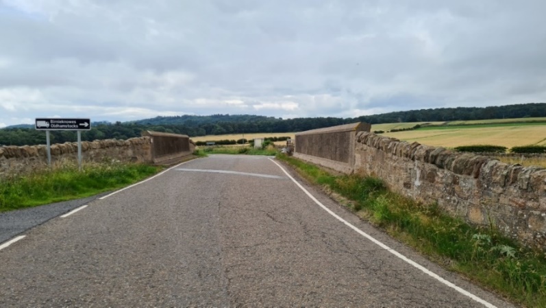
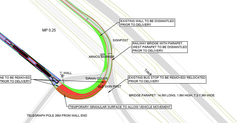
Figure 4‑1 Railway bridge Crossing for Delivery to Substation Location 3
4.2 Substation Location 8 & 9
The delivery route to the proposed substation location 8 and 9 will require the delivery vehicle to traverse a culvert. The location of the culvert is shown in Figure 4‑2. The make-up of the culvert could not be confirmed due to dense and overgrown vegetation.
An assessment of the culvert for the abnormal load is required. Note that no information was determined on the details of the culvert due to overgrown bushes and limited access.
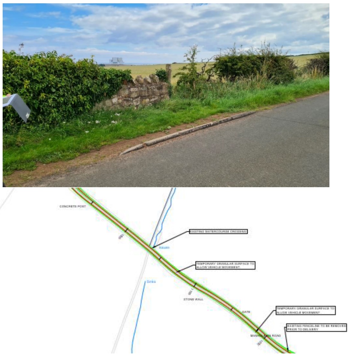
Figure 4‑2 Culvert Road Crossing for Deliver to Substation 8 & 9
4.3 HGV - Cable Road Crossing 1
The delivery route to the trenched cable road crossing 1 will required the HGV to cross a railway bridge. The location of the bridge is shown in Figure 4‑3.
An assessment of the railway bridge crossing for the HGV is required.
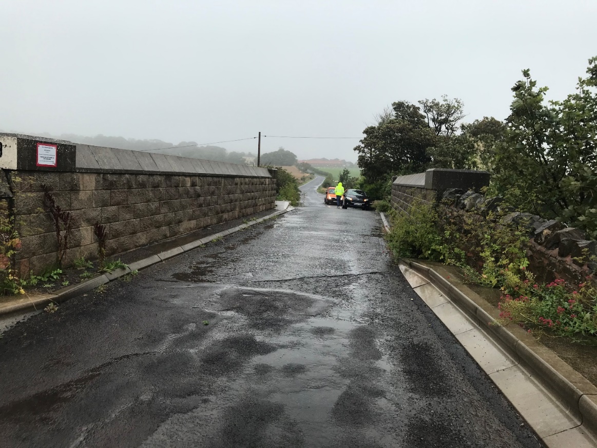
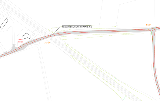
Figure 4‑3 Railway Bridge Crossing for Cable Road Crossing 1
4.4 HGV - Cable Road Crossing 2
The delivery route to the trenched cable road crossing 2 will require the HGV to cross a watercourse crossing. The location of the crossing is shown in Figure 4‑4.
An assessment of the watercourse crossing for the HGV is required. Note that limited details and dimensions of the bridge were obtained due to restricted access.
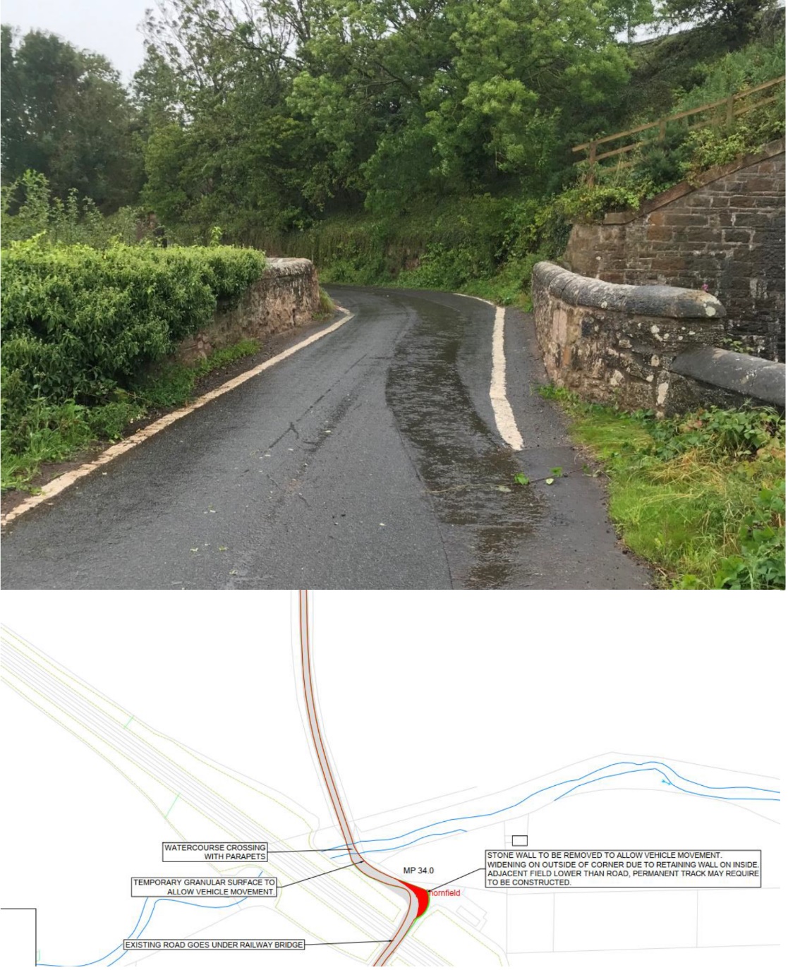
Figure 4‑4 Watercourse Crossing for Cable Road Crossing 2
5 Permanent Access Road Proposal
No ground investigation reports have been provided at this stage with respect to design of the permanent access roads. Therefore, proposals for the following road make-up have been provided in appendix D:
- Floating access track (level or gently sloping topography);
- Founded access track (level or gently sloping topography);
- Founded access track – Track Construction Benched (on sloping topography).
6 Construction Cost Estimate
A cost estimate (+25%/-15%) for the new access road construction and improvements to current infrastructure has been assessed using values calculated from Spon’s Civil Engineering and Highways Work Price Book, the Estimator’s Pocket Book and information provided by contractors.
A preliminary assessment of the permanent access road was undertaken in lieu of ground investigation information. This assessment considered data from British Geological Survey maps. Given the road construction cost is sensitive to change and accounts for most of the overall cost, a lower and upper bound cost was used in the estimations.
Areas of temporary granular fill are based on vehicle overrun only. Earthwork requirements are subject to more detailed review as part of route temporary works design.
An estimate of the costs for each substation route is presented in Table 7 with the detailed estimate presented in Appendix E.
Table 7 - Substation Access Road Construction Cost Estimate
Substation | Estimated Construction Cost Range | |
Substation Location 3 | £506,243 | £862,806 |
Substation Location 8 | £187,111 | £278,978 |
Substation Location 9 | £225,646 | £348,842 |
It is advised to obtain a more detailed cost estimate from several contractors once topographical data and ground investigation information are made available. Note prices will vary between contractors and are subject to market conditions.