

3.6. The Need for the Proposed Development
The need for the Proposed Development can be considered from two perspectives: (i) the policy-based need for the Proposed Development; (ii) the practical need for the Proposed Development. Each perspective is considered, below.
3.6.1. The Policy-Based Need for the Proposed Development
As documented in Section 3.2 of this Scoping Report, by falling within the scope of NPF3’s national development number 4, the need for the Proposed Development is established in the context of Scottish planning policy. This is recognised in ELC LDP policy.
In the context of the wider Scottish and UK energy policy discussed within Section 3.5 of this Scoping Report, the need for the Project, focussed upon the role of offshore wind energy as part of a sustainable long-term mix of generating sources across Scotland and the UK, is established. The Project will contribute towards Scotland’s climate change targets, specifically 2045 net-zero targets.
3.6.2. The Practical Need for the Proposed Development
As part of the Project, the policy-based need for the Proposed Development is established, and therefore, the practical need for the Proposed Development is clear.
The Proposed Development is needed to connect a major offshore wind electricity generating facility to the national electricity transmission grid. Without such a connection the electricity generated offshore could not connect to the grid and in turn, could not be used to power residential, commercial and other properties across East Lothian, Scotland and the UK.
3.7. References
- East Lothian Council (2018). Local Development Plan. Available at: https://www.eastlothian.gov.uk/info/210547/planning_and_building_standards/12242/local_development_plan/2
- Marine Scotland (2011). Sectoral Marine Plan for Offshore Wind Energy (Blue Seas Green Energy). Available at: https://www2.gov.scot/Topics/marine/marineenergy/wind
- Marine Scotland (2015). National Marine Plan. Available at: https://www.gov.scot/publications/scotlands-national-marine-plan/
- Scottish Executive (1997). Town and Country Planning (Scotland) Act 1997 (as amended by the Town and Country Planning (Scotland) Act 2019). Available at: http://www.legislation.gov.uk/ukpga/1997/8/contents
- Scottish Government (2014a). National Planning Framework 3. Available at: https://www2.gov.scot/Topics/Built-Environment/planning/NPF3-SPP-Review/NPF3
- Scottish Government (2014b). Scottish Planning Policy. Available at: https://www.gov.scot/publications/scottish-planning-policy/
- Scottish Government (2017). The Scottish Energy Strategy: The Future of Energy in Scotland. Available at: https://www.gov.scot/publications/scottish-energy-strategy-future-energy-scotland-9781788515276/
- Scottish Government (2019b). Draft Sectoral Marine Plan for Offshore Wind Scottish Government (2019a). The Climate Change (Emissions Reduction Targets) (Scotland) Act 2019. Available at: http://www.legislation.gov.uk/asp/2019/15/enactedEnergy. Available at: https://www2.gov.scot/Topics/marine/marineenergy/Planning/draftSMPcons2019
- Scottish Government (2019c). The Draft Offshore Wind Energy Policy Statement. Available at: https://www.gov.scot/publications/draft-offshore-wind-policy-statement/
- Scottish Government (various). Planning Advice Notes. Available at: https://www.gov.scot/collections/planning-advice-notes-pans/
- The Strategic Development Planning Authority for Edinburgh and South East Scotland (2013). Strategic Development Plan. Available at: https://www.sesplan.gov.uk/assets/files/docs/290813/SESplan%20Strategic%20Development%20Plan%20Approved%2027%20June%202013.pdf
- OVERVIEW OF SITE SELECTION PROCESS
- Introduction
Introduction
OVERVIEW OF SITE SELECTION PROCESS Introduction
The Applicant has a grid connection agreement with National Grid Electricity System Operator at a point close to the existing Branxton compound, approximately 8 km south of Dunbar.
From this, the Applicant has considered a number of landfall and substation options within the vicinity of Branxton. These have been evaluated from an engineering, consents (planning and environment), land use and cost perspective.
4.2. Site Selection
The following process has been followed to identify the key infrastructure sites currently being considered within the Search Area for the Site Boundary:

Diagram 4.1: Site Selection Process Overview
Note that reference to landfall 3 is the Skateraw landfall option, landfall 5 is the Thorntonloch landfall option, substation 3 is the Thorntonloch Holdings substation option, substation 8 is the Skateraw substation option and substation 9 is the Crowhill substation option.
The preferred indicative options, shown on Figure 5.1 and further detailed in Chapter 5 below, will continue to be refined as part of the iterative design process of the Proposed Development.
- PROPOSED DEVELOPMENT DESCRIPTION
- Introduction
Introduction
PROPOSED DEVELOPMENT DESCRIPTION Introduction
This chapter provides a description of the Search Area for the Site Boundary and its geographical context, and also presents a description of the Proposed Development.
As per Section 1.4, the Proposed Development consists of the onshore infrastructure of the Project down to MLWS.
5.2. Search Area for the Site Boundary
The Search Area for the Site Boundary is situated near Torness and the village of Innerwick, south-east of Dunbar located in East Lothian, Scotland (refer to Figure 1.1). The centre of the site boundary is OSGB36, British National Grid (BNG) 373976, 674081. The site is approximately 678.9 ha in size. It should be noted that the final Planning Application Boundary will be smaller than that shown in Figure 1.1 as it will be refined through further investigations and design evolution processes.
The site runs from the hamlet of Branxton in the south, Bilsdean in the south-east, the coastline at Thorntonloch and Torness in the north-east, Oxwell Mains Cement Works and Quarry and the coastline at Chapel Point in the north, and Fouracres in the west. The area is predominantly agricultural land with sparse hamlets and villages spread throughout the area connected by small local roads and tracks. The A1 trunk road and East Coast Main Line (ECML) railway cut through the centre of the site in a north-west to south-east direction running parallel to the coast. The Torness Nuclear Power Station is located to the north-east of the site, between the two points where the Search Area for the Site Boundary meets the North Sea.
Ground levels within the site vary due to the sloping topography (west to east) and due to deeply incised glacial outwash valleys.
The main existing infrastructure within the site and adjacent area is:
- Torness Nuclear Power Station and associated infrastructure (jetties, outfalls and cables);
- Torness nuclear waste railway loading dock;
- A1 trunk road;
- ECML railway;
- the two existing cable sealing end compounds at Branxton;
- existing 400 kV Overhead Lines and Underground Cables at Branxton
- Innerwick electricity substation associated with the ECML railway; and
- utilities, including water, gas and electricity services.
Chapter 4 provides a summary of the collaborative engineering and environmental consideration which have informed the site selection process and the potential options the Applicant is currently investigating.
5.3. Proposed Development
The Proposed Development comprises the onshore elements of the Project, and consists of the following;
- up to two landfall locations and transition pits;
- a new wind farm onshore substation;
- the connecting primarily underground onshore cables (between landfall(s) and the new substation and between the new substation and the grid connection substation) with the option of a short section of OHL and cable bridge (which may be the subject of a separate application under the appropriate legislation);
- potential new and upgraded access tracks to the substation, cable construction corridor and landfall(s); and
- associated ancillary infrastructure.
The lifetime of the Proposed Development is currently anticipated to be 50 years from the commencement of operation to commencement of decommissioning.
5.3.1. Landfalls and Transition Pits
A landfall is where the offshore (sub-marine) export cables come to shore and are connected to the onshore cables at a buried transition pit. The Proposed Development will either have one transition pit for each cable or one large transition pit for all cables. The transition pit(s) will comprise a box-like structure where the cables will be buried. The dimensions of the transition pits will be determined following more detailed assessment.
5.3.1.1. Landfall Options
The Applicant is currently considering two different landfall options, one or both will be used to land the cables from the offshore infrastructure (refer to Figure 5.1):
- Landfall 3 (hereafter referred to as Skateraw landfall option) – BNG 373619, 675786; and
- Landfall 5 (hereafter referred to as Thorntonloch landfall option) – BNG 375457, 673893
Skateraw landfall option is located near Skateraw at Chapel Point, north-west of Torness Power Station. This area is mainly rocky shore, with small areas of sand. The landfall would intersect the Barns Ness Coast Geological Site of Special Scientific Interest (SSSI) and the John Muir Link coastal path.
From the landfall the cable would be routed underground through an area of relatively flat agricultural land to the transition pit, located approximately 170 m north-west of Skateraw harbour and then onto the substation.
Thorntonloch landfall option is located on Thorntonloch beach, south of Torness Power Station. This area is sandy beach and is designated as ‘bathing waters’ by SEPA. The John Muir Link coastal path would also be intersected by Thorntonloch landfall option.
From the landfall the cable would be routed underground through an area of agricultural land located on a gentle, north-eastern facing slope between Thorntonloch beach and the A1 trunk road to the transition pit and then onto the substation. The transition pit would be located approximately 500 m south-east of Thorntonloch on land used for arable agriculture.
In respect of both landfalls, the cable route option beyond the transition pits will depend on the final substation site selection.
5.3.2. Substation
The onshore substation will either be a High Voltage Alternating Current (HVAC) Substation comprising of external HV equipment and Gas Insulated Switchgear; or a High Voltage Direct Current (HVDC) substation comprising of a converter building, HV external equipment and Gas Insulated Switchgear. For the remainder of this EIA Scoping Report the generic term “substation” is used to cover both scenarios. The substation will contain electrical components for transforming the power supplied from the wind farm to the grid voltage.
The footprint of the substation infrastructure is anticipated to be approximately 360 m (length) by 250 m (width) by 20 m (height – 26 m including aerials and lightening conductors). The substation will include, but is not limited to, transformers, switchgear, coolers, harmonic filters, reactive power compensation equipment, common building, Gas Insulated Switchgear (GIS) building (if selected), Converter Hall (if HVDC is selected) blast walls, industrial low voltage systems, heating, ventilation and air conditioning. The equipment will be both housed inside buildings and located outside. The configuration of buildings and external equipment (worst case) will be defined within the planning application in order to facilitate assessment of the Proposed Development; however, the final specifications will be the subject of a planning condition, to be approved by ELC prior to the commencement of substation structures.
In addition to the aforementioned substation infrastructure, it is anticipated that there will be landscaping, security fencing, car parking and drainage in the land around the substation.
5.3.2.1. Substation Options
The Applicant is currently considering three potential substation locations, from which one option will be progressed:
- Substation 3 (hereafter referred to as Thorntonloch Holdings substation option): BNG 374586, 673725
- Substation 8 (hereafter referred to as Skateraw substation option): BNG 373348, 674627
- Substation 9 (hereafter referred to as Crowhill substation option): BNG 373748, 674392
Thorntonloch Holdings substation option is located in an agricultural field, on a north-eastern facing slope approximately 650 m south-east of Thorntonloch and 400 m north-east of Thornton (refer to Figure 5.1). The land is currently used for arable agriculture. The ECML railway is located 135 m to the north and the A1 trunk road and NCR76 are located approximately 420 m to the north-east.
Skateraw substation option is located on an agricultural field, at the bottom of a gentle north-eastern facing slope approximately 350 m south of Skateraw, and 380 m north of Crowhill (refer to Figure 5.1). The land is currently used for arable agriculture. The ECML railway is located 80 m to the north-east and the A1 trunk road 150 m to the north.
Crowhill substation option is located in an agricultural field, on a gentle north-eastern facing slope approximately 550 m south-east of Skateraw, and 180 m north of Crowhill (refer to Figure 5.1). The land is currently used for arable agriculture. The ECML railway is located 110 m to the north and the A1 trunk road are located approximately 280 m to the north. There is also an existing small substation, operated by Scottish Power Energy Networks and Network Rail, 110 m east of Crowhill substation option.
5.3.3. Access Roads
Permanent, surfaced single carriageway roads with passing places, to connect the substation to the public highway will be constructed. These will be private and include appropriate drainage.
In addition, some sections of the public roads may require permanent widening, resurfacing or passing places added to allow access to the Proposed Development site. Any proposed road works will be agreed with ELC.
5.3.4. Onshore Cable Routes
Various options to connect the transition pit(s) to the substation, and the substation to the grid connection point (a new Scottish Power Energy Networks substation being progressed under a separate consenting process) are being considered. The preferred route will be selected following the determination of the substation, landfall location(s), requirements of grid connection, and the undertaking of more detailed investigations.
The cable route from landfall(s) to the substation will intersect the A1 trunk road and ECML railway. Here, trenchless techniques will be employed (refer to below).
Based on the preferred substation, the cable route from the new substation to the substation grid connection will intersect with Thornton Burn.
The proposed cable route will be underground, however a short section of OHL and a cable bridge may be required.
5.3.5. Drainage
Permanent drainage may be required for the substation site and along the cable route. The design and locations of this will be developed as the Proposed Development progresses and will meet national standards and guidance.
5.4. Construction Phase
Construction of the Proposed Development is anticipated to take approximately 36 months, commencing in 2025, following consent in 2022. The exact construction methodologies for the permanent infrastructure are yet to be determined, however potential options are described below. The design and the construction methodology (including required temporary infrastructure) will be determined in advance of the planning application submission and included in the EIAR.
The EIAR will include appropriate assumptions in respect of construction phasing. A detailed construction phasing plan will be submitted for ELC approval pursuant to a planning condition and may include:
- Landfall(s);
- Cable enabling works;
- Cable route construction;
- If required, cable bridge and OHL construction;
- Substation enabling works;
- Substation civils works;
- Substation structural works. and [2]
- Substation electrical installation works
Discharge of planning conditions will relate to agreed phases of construction.
Normal construction hours will be Monday to Sunday 07.00-19.00.
If these times require to be controlled this will be agreed with ELC via an appropriately worded condition. Details of the construction programme will be provided to ELC in the Construction Environmental Management Plan (CEMP) prior to the commencement of construction and secured via an appropriately worded planning condition.
Any construction outwith these hours, due to construction time constraints (e.g. specific works are required to be undertaken within one session), weather windows and/or health and safety requirements, will be in line with the noise limits and advance warning of any works outwith the normal working hours will be provided to ELC Environmental Services and local residents.
5.4.1. Construction Environmental Management Plan (CEMP)
As part of the construction contract, the Applicant and their Contractor will develop, and adhere to, a CEMP which will cover all aspects of the Proposed Development and describe how the Contractor will ensure the suitable implementation and control of the mitigation measures described in the EIAR.
5.4.2. Landfalls and Transition Pits
5.4.2.1. Methodology
The offshore cable will be brought to shore using trenchless technology or open cut trenching (refer to the Glossary). The offshore cable will be pulled from sea to land, while the drill, or trench, will be constructed from land to sea.
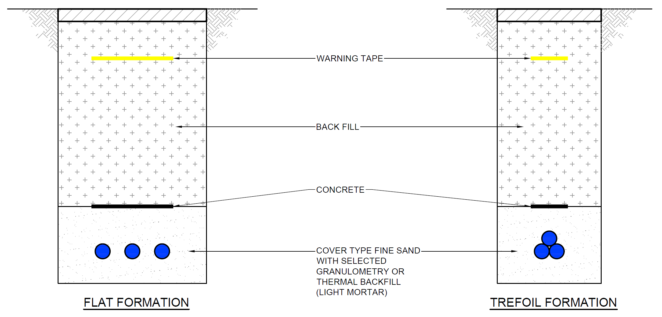
Drawing 5.1: Typical Cross-Section of Open Trenching Method
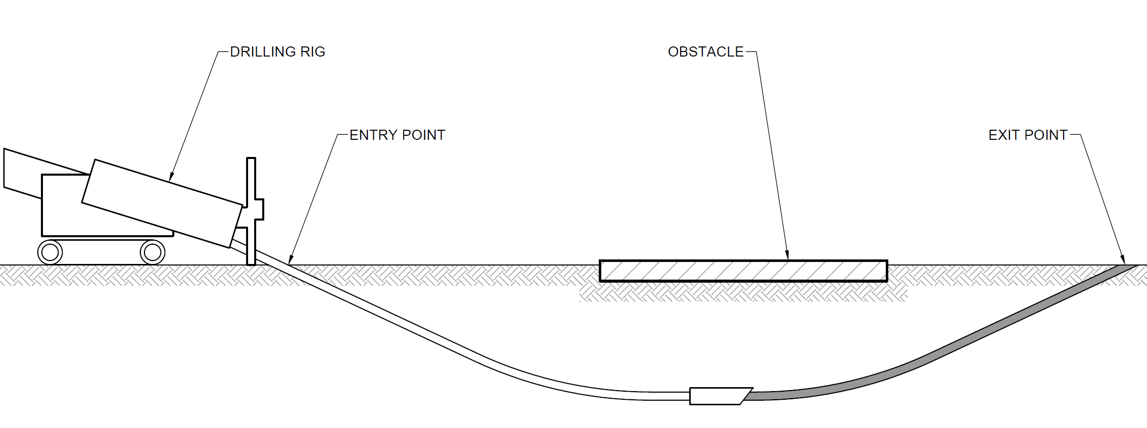
Drawing 5.2: Typical Long-Section of HDD Method[3]
The transition pit(s) will be dug using the same methodology as open cut trenching. Following construction and installation, the transition pit(s) will be back-filled with only minor structures being visible above ground such as a low link pillar for earthing requirements and potentially fencing. Other smaller excavations in the vicinity may also be necessary for fibre optic link joints and earthing requirements.
5.4.2.2. Temporary Infrastructure
During construction a temporary welfare and construction compound will require to be built adjacent to the transition pit(s). The size of the construction compound is not yet known and will depend upon the construction methodology but may range from 4,000-10,000 m2.
Temporary access tracks to the landfall and transition pit(s) may be required to be built to connect the landfall and transition pit(s) to the public highway.
5.4.3. Substation
5.4.3.1. Methodology
The construction of the substation is anticipated to require the following:
- Construction of spread foundations to support small structures and pavements including car parking;
- Construction of piled foundations to support the high loads of the transformers;
- Construction of a flat platform. The exact depth and volume of cut and fill will be determined following more detailed investigations. Depending on the topography this may require the construction of retaining structures;
- Installation of utilities and services;
- Installation of drainage and construction of attenuation pond;
- Installation of substation infrastructure; and
- Landscaping, fencing and restoration of site.
- Temporary Infrastructure
It is anticipated that a construction compound of similar sizing to the substation will be required nearby to the substation during construction. It will generally include welfare facilities, portacabin office(s), plant and equipment, laydown areas, and car parking.
5.4.4. Access Tracks
5.4.4.1. Methodology
Sections of existing roads may require widening, specifically on bends and require passing laybys, or resurfacing. Where possible impacts to trees and hedgerows along existing roads will be minimised. The selection of these roads and the dimensions for widening/upgrading will be developed prior to submission of the application. The upgrading of temporary and permanent access roads will be carried out to an acceptable standard to accommodate abnormal load delivery vehicles.
5.4.4.2. Temporary Infrastructure
Temporary borrow pit(s) may be required to provide aggregate for the construction of the substation and access roads. The requirement for borrow pit(s), their location, and their method of excavation will be determined through more detailed investigations and reported within the EIAR. Land affected by temporary works will be reinstated upon completion of such works.
5.4.5. Onshore Cables
5.4.5.1. Methodology
Open cut trenching will be required for the majority of onshore cable route installation with trenchless technology being considered for landfall, to cross infrastructure such as underground cables, the A1 trunk road and ECML railway (refer to the Glossary). The preferred technique(s) will be determined through more detailed investigations.
There is also potentially a requirement for piled foundations to support bridge crossings of watercourses and OHL, if such structures are required.
5.4.5.2. Temporary Infrastructure
Depending on the cable route there is potential for several small construction compounds to be located along the cable route.
5.4.6. Drainage
During construction temporary Sustainable Urban Drainage Systems (SUDS) will be constructed around the temporary infrastructure (access tracks and construction compounds) to manage and control surface run-off.
Prior to commencement of construction activities, a pollution prevention plan, part of a Construction Site Licence, will be approved by SEPA to ensure that appropriate measures are put in place to protect watercourses and the surrounding environment.
5.4.7. Water Abstraction
As well as water being tanked into the Proposed Development site for use during construction, water may also be obtained from the site e.g. pumped from boreholes. If water is to be abstracted from the site for use in construction the Applicant will provide an assessment of this within the EIAR and submit appropriate Controlled Activities Regulations (CAR) applications to SEPA.
5.5. Operation & Maintenance Phase
The Proposed Development will be managed, operated and maintained initially by Berwick Bank Wind Limited and then Offshore Transmission Owners for the duration of its lifetime, currently anticipated at 50 years.
During operation access will be required to the Proposed Development for operation and maintenance activities 24 hours per day, 365 days per year, however the Proposed Development will not be permanently staffed.
Security at the substation during operation will comprise likely appropriate fencing, CCTV and access control systems. It is anticipated that fencing may also be required at the transition joint bays along the cable route.
5.6. Decommissioning Phase
For the purpose of the EIA the Applicant assumes that the decommissioning will occur 50 years after the commencement of operation and will take 18-24 months to complete.
The methodology for decommissioning will be similar to that described above for construction, but in reverse. It is anticipated that all the infrastructure will be removed with the exception of buried ducting, the foundations of the substation and any bridge crossings outwith the top 1 m of the reinstated surface level. It is anticipated that a Decommissioning Plan will be required by a planning condition, to be approved by ELC prior to the commencement of decommissioning activities.
- ENVIRONMENTAL IMPACT ASSESSMENT METHODOLOGY
- Introduction
Introduction
ENVIRONMENTAL IMPACT ASSESSMENT METHODOLOGY Introduction
This chapter describes the general methodology that will be applied to the Proposed Development EIA for the identification and evaluation of potential likely significant environmental effects (as defined in the 2017 EIA Regulations) and presents the proposed methodology for the identification and evaluation of potential cumulative and inter-related impacts. A systematic and auditable evidence-based approach will be followed to evaluate and interpret the potential effects on physical, biological and human receptors.
This methodology may alter slightly between technical topics due to topic specific best-practice EIA guidance (for example by the Landscape Institute or the Chartered Institute of Ecology and Environmental Management), however the fundamental principles will remain the same. Within the EIAR each technical chapter will provide a detailed methodology of how their assessment has been undertaken.
6.2. Regulations & Guidance
The EU Directive on the assessment of the effects of certain public and private projects on the environment (EIA Directive) (2011/92/EU, as amended by Directive 2014/52/EU) states that when applying for Section 36 consent, a marine licence or planning permission, an EIAR is required to be prepared and submitted to support these applications if they are likely to have a significant effect on the environment due to factors such as their size nature or location.
The Town and Country Planning (Environmental Impact Assessment) (Scotland) Regulations 2017 apply the EIA Directive in a local context.
As per Section 1.5, the Applicant is voluntarily undertaking an EIA as the Applicant accepts that an EIA is required for the Proposed Development.
In addition to the legislative requirements, guidance and best practice documents have been developed to assist with the production of a ‘fit for purpose’ and proportionate EIA. Topic specific documents are detailed in technical Chapters 7-16, while overarching EIA guidance documents are listed below:
- IEMA Environmental Impact Assessment Guide to Shaping Quality Development (IEMA, 2015);
- Delivering Proportionate EIA, A Collaborative Strategy for Enhancing UK Environmental Impact Assessment Practice (IEMA, 2016);
- Planning Advice Note (PAN) 1/2013 Environmental Impact Assessment (Scottish Government, 2017);
- A Handbook on Environmental Impact Assessment (SNH, 2018).
- EIA Process
EIA Process
EIA is an iterative process and through the identification of environmental receptors and the assessment of potential impacts, it influences the design of the Proposed Development. It can also influence the proposed construction, operation and decommissioning methodologies to ensure the environmental impacts of the Proposed Development are removed or reduced, where appropriate.
To achieve this, and to ensure a proportionate EIA, mitigation is classified into three types:
- Primary – mitigation which is part of the proposed development’s design;
- Secondary – mitigation which requires further activity, identified through the EIA process, e.g. implementation through the CEMP or planning conditions; and
- Tertiary – mitigation which will be implemented regardless of the design process and the EIA, i.e. the mitigation outlined in Annex A of this Scoping Report and which will also be included within the CEMP
The application of these in the EIA process is demonstrated in Diagram 6.1.

Diagram 6.1: The Approach to Mitigation within the EIA Process
6.3.1. Characterisation of the Environmental Receptors (the Baseline)
The baseline environmental receptors for each technical topic will be determined through consultation and a range of desk-based research and site surveys.
Following the identification of the environmental receptors their sensitivity will be identified. The methodology for determining sensitivity will differ between technical topics and will be based on a number of factors which may include (depending on the topic):
- statutory or non-statutory designation;
- prevalence;
- vulnerability; and
- usage.
- Identification of Tertiary Mitigation
As per Section 2.2, to ensure a proportionate EIA this Scoping Report, and the EIAR will assume that a range of mitigation measures will be embedded within the Proposed Development. These mitigation measures will be undertaken by the Applicant, no matter the findings of the EIA, or whether or not the measures are specifically required by the planning permission, and are therefore part of the Proposed Development, rather than in addition to the Proposed Development. Implementation of these mitigation measures will be controlled through a planning condition linking the approved development to the EIAR.
Annex A provides an Outline Schedule of Environmental Commitments (OSEC). This OSEC details all the tertiary mitigation measures and will be expanded upon within the EIA following the assessment with any additional specific mitigation measures.
6.3.3. Assessment of Potential Effects
As per Section 2.2, throughout the EIAR a distinction will be made between the term ‘impact’ and ‘effect’. An impact is defined as the likely change to the characteristics/nature of the receiving environment (the ‘receptor’), whereas the ‘effect’ relates to the significance of the impact. The level of significance of effect is determined by considering both the value of the receptor (its ’sensitivity’) and the magnitude of the impact.
The exception to this is the Landscape and Visual Impact Assessment which classifies the level of physical and perceptual change to the receiving environment as the ‘magnitude of change’ in line with the recommendations of the Guidelines for Landscape and Visual Impact Assessment third edition (GLVIA3) (Landscape Institute, 2013). However, this terminology should be considered interchangeable with ’’magnitude of impact’.
Within the EIAR, the assessment of effects for each environmental topic will take into account the environmental impacts of both the construction/decommissioning and operational phases of the Proposed Development and the environmental impacts should the Proposed Development not be consented (the do-nothing scenario).
To determine whether or not the potential effects of the Proposed Development are likely to be ‘significant’ a number of criteria are used. These significance criteria vary between topics but generally include:
- international, national and local designations or standards;
- relationship with planning policy;
- sensitivity of the receiving environment;
- magnitude of impact;
- reversibility and duration of the impact; and
- inter-relationship between impacts.
Effects that are considered to be significant, prior to secondary mitigation but following the implementation of best practice (tertiary mitigation), are identified within the EIAR. The significance attributed to the resultant effect is informed by professional judgement, as to the sensitivity of the affected receptor(s) and the nature and magnitude of the predicted changes/impacts. For example, a major adverse change/impact on a feature or site of low importance will have an effect of lesser significance than the same impact on a feature or site of high importance. Table 6.1 below is used as a guide to the relationship between the sensitivity of the identified receptor and the anticipated magnitude of an impact/change. Professional judgement is however equally important in establishing the suitability of this guiding ‘formula’ to the assessment of the significance of each individual effect.
Table 6.1: Significance of Effects Matrix
The following terms are used in the EIAR, unless otherwise stated, to determine the level of effects predicted to occur:
- major beneficial or adverse effect – where the Proposed Development would result in a significant improvement (or deterioration) to the existing environment;
- moderate beneficial or adverse effect – where the Proposed Development would result in a noticeable improvement (or deterioration) to the existing environment;
- minor beneficial or adverse effect – where the Proposed Development would result in a small improvement (or deterioration) to the existing environment; and
- negligible – where the Proposed Development would result in no discernible improvement (or deterioration) to the existing environment.
Using professional judgement and with reference to the Guidelines for Environmental Impact Assessment (IEMA, 2004), the majority of the assessments within this EIAR consider effects of moderate or major to be significant (those highlighted orange to red within Table 6.1). Those of minor or negligible effect are deemed to be non-significant (yellow, green and white within Table 6.1). Professional judgement will be used to determine whether an effect of minor-moderate significance is considered significant or non-significant. If there are deviations from this these will be clearly stated within the individual technical chapters.
Summary tables that outline the predicted effects associated with an environmental topic, will be provided at the end of each technical chapter of the EIAR. Distinction will also be made between direct and indirect, short and long term, permanent and temporary, beneficial and adverse effects.
6.3.4. Identification of Primary Mitigation
Primary mitigation alters the design of the Proposed Development, or associated construction, operation or decommissioning methodologies in order to reduce or remove the potential significant effects. Primary mitigation is an intrinsic part of the design of the Proposed Development and as such will be reported within the Design Chapter of the EIAR.
6.3.5. Identification of Secondary Mitigation
Should significant effects be identified which cannot be mitigated through the implementation of the primary or tertiary mitigation, secondary mitigation will be identified to further remove/reduce the significant adverse effects. In addition, should environmental monitoring measures be required during the Proposed Developments lifecycle, these will be detailed here.
This secondary mitigation, along with the tertiary mitigation will be compiled within a Schedule of Mitigation within the EIAR and the Applicant will commit to implementing these mitigation measures.
6.3.6. Assessment of Residual Effects
Following the identification of secondary mitigation measures, the assessment of effects will be re-assessed to determine the residual effects using the same methodology as the assessment of the potential effects, but assuming the implementation of the mitigation.
6.3.7. Inter-related Effects
Consideration will be given within the EIAR to the inter-relationship of effects between topics (e.g. impacts on an ecology and hydrology receptor). The assessment of potential inter-related effects will consider two levels of effects:
- Proposed Development lifetime: effects within a topic occurring throughout the lifetime of the Proposed Development, across more than one phase (construction, operation and decommissioning); and
- receptor led: cross topic effects that interact spatially and/or temporally resulting in greater effects upon a single receptor than when considered in isolation.
- Transboundary Effects
The Proposed Development would not have transboundary effects and therefore this will not be considered further within the EIA Scoping Report or the EIAR.
6.3.9. Cumulative Impact Assessments
A cumulative impact assessment (CIA) is a legal requirement under the 2017 EIA Regulations. A CIA provides consideration of the impacts arising from the Proposed Development alone and cumulatively with other relevant developments. Cumulative effects are therefore the combined effect of the Proposed Development in combination with the effects from a number of different projects, on the same receptor or resource.
Each technical chapter within the EIAR will undertake a cumulative assessment. Potential cumulative developments within the technical assessment study areas will be screened to determine whether there is potential for overlap of environmental effects with the Proposed Development. Where there is potential for cumulative effects to occur, each environmental receptor will be screened, based on the technical expertise of the assessment team. If the receptor is screened in, the cumulative assessment will then consist of two tiers:
- Tier 1: A cumulative assessment of the effects to onshore receptors from both onshore and offshore infrastructure of the Project.
- Tier 2: A cumulative assessment of the Project in combination with other proposed (in planning) and consented developments in the onshore environment.
Tier 1: Cumulative Assessment with Offshore Infrastructure
The cumulative assessment of onshore and offshore infrastructure will identify and assess whether there is potential for receptors to be impacted by both the onshore and offshore infrastructure of the Project and what that cumulative effect is anticipated to be.
For some receptors there will be no cumulative impact from the onshore and offshore infrastructure, they will only be affected by one or another. Where this is the case cumulative assessment with offshore infrastructure will be scoped out of the assessment.
However, where there is potential for the receptor to be impacted by both the onshore and offshore infrastructure (e.g. a viewpoint or a migratory species) the assessment will consider both impacts and determine the cumulative effect.
Tier 2: Cumulative Assessment with Other Onshore Developments
Following the cumulative assessment with offshore infrastructure the EIA will then undertake a cumulative assessment of the Project (onshore and offshore infrastructure) with other onshore projects[4]. Only projects which are in planning, consented or under construction will be considered within the cumulative assessment.
As noted in Chapter 2, and as per Scottish Planning Policy (Scottish Government, 2014) only developments which are submitted to planning, consented or under construction will be considered cumulatively.
This list of cumulative developments will continually be updated throughout the assessment of the Proposed Development and any exceptional circumstances considered. However, the list will be “frozen” three months prior to the submission of the application to allow assessments to be made and reported within the EIAR.
The Applicant would be grateful for any further information which ELC may hold on these projects or other projects that ELC believe should be included within the cumulative assessment.
6.4. EIA Report
The EIA will be reported within an EIAR whose structure will follow the requirements of the 2017 EIA Regulations and other relevant good practice guidance (refer to Section 6.2 above). Essentially the EIAR will comprise four main parts:
- a non-technical summary (NTS);
- the main EIA text;
- accompanying figures; and
- technical appendices.
The front-end of the main EIA text will comprise of:
- an introduction;
- a description of the site selection and design iteration process;
- a description of the Proposed Development and the good practice implemented during construction, operation and decommissioning; and
- a description of the EIA process and the consultation undertaken.
The remainder of the document will present an assessment of each technical topic (e.g. noise, cultural heritage, etc.) which will each be provided in a separate technical chapter.
6.5. References
- EC (1985). EIA Directive (85/337/EEC). Available at: https://ec.europa.eu/environment/eia/eia-legalcontext.htm
- IEMA (2015). IEMA Environmental Impact Assessment Guide to Shaping Quality Development. Available at: https://www.iema.net/assets/uploads/iema_guidance_documents_eia_guide_to_shaping_quality_development_v7.pdf
- Scottish Government (2013). Planning Advice Note (PAN) 1/2013 Environmental Impact Assessment. Available at: https://www.gov.scot/publications/planning-advice-note-1-2013-environmental-impact-assessment/
- Scottish Government (2017). The Town and Country Planning (environmental Impact Assessment) (Scotland) Regulations 2017. Available at: http://www.legislation.gov.uk/ssi/2017/102/contents/made
- SNH (2018). A Handbook on Environmental Impact Assessment. Available at: https://www.nature.scot/handbook-environmental-impact-assessment-guidance-competent-authorities-consultees-and-others
- LANDSCAPE AND VISUAL
- Introduction
Introduction
LANDSCAPE AND VISUAL Introduction
The following chapter presents the proposed approach to the assessment of potential effects of the Proposed Development on landscape and visual receptors.
7.2. Study Area
The Landscape and Visual Impact Assessment (LVIA) study area will extend to define a limit beyond which it is considered unlikely that significant effects would arise (the LVIA study area is shown on Figure 7.1). For the Proposed Development this consideration is based on a combination of Zone of Theoretical Visibility (ZTV) mapping and professional judgement in relation to the degree of effect likely to arise. This professional judgement is based on knowledge of similar projects (including the scale of the built elements of the Proposed Development) and an understanding of the character and visual resource of the local landscape.
The ZTV preparation carried out at scoping stage includes analysis of each of the three indicative substation options modelled at a height of 20 m (worst realistic case described in the development description) for each of the substation site areas (refer to Figures 7.5-7.7). These theoretical visibility maps provide an indicative level of theoretical bare ground visibility that helps to discern the level of potential visibility within the surrounding landscape. Following the selection of the final substation location, further ZTVs will be produced using the maximum building height and footprint of the substation.
Taking this into account, the scoping stage onshore substation LVIA study area covers the following
- a 5 km radius from the three onshore substation options; and
- a 1 km radius from the landfalls and potential onshore cable route corridor (all of which are found within the wider 5 km substation study area).
The study area will be refined in the EIAR, once the final location of the Proposed Development infrastructure has been determined.